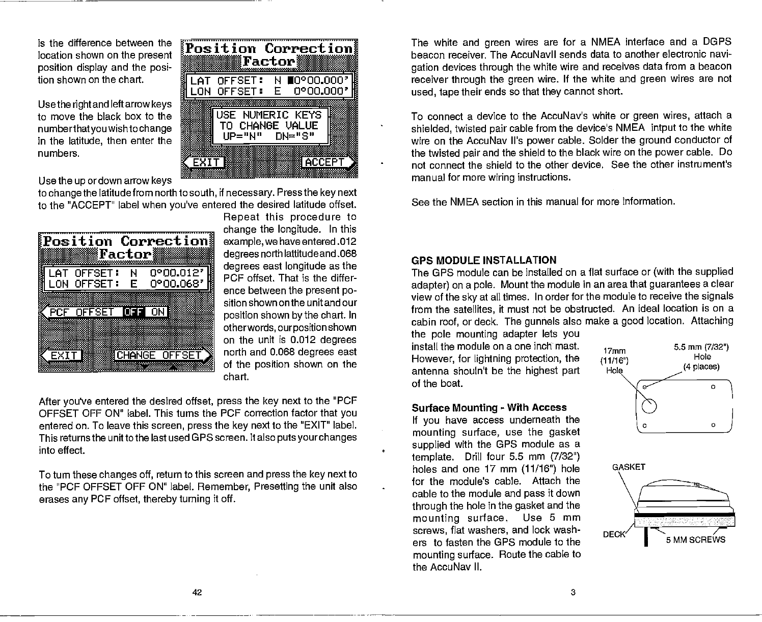
is the
difference between the
location shown on
the
present
position display
and the
posi-
tion shown on the
chart.
Use the
right
and left arrow
keys
to move the black box to
the
numberthatyou
wish to
change
in the
latitude,
then enter the
numbers.
Use the
up
ordown arrow
keys
Position
Correction
flflr
flFsET:NIooOO.oOO
MOO'
to
change
the latitude from north to
south,
if
necessary.
Press the
key
next
to the "ACCEPT" label
when
you've
entered the desired latitude offset.
Repeat
this
procedure
to
the
longitude.
In this
example,
we have entered .012
degrees
north lattitude
and .068
degrees
east
longitude
as the
PCF
offset. That is the differ-
ence between the
present po-
sition shown
onthe unitand our
position
shown
by
the chart. In
otherwords,
ourposition
shown
on the unit is 0.012
degrees
north and 0.068
degrees
east
of the
position
shown on the
After
you've
entered the desired
offset,
press
the
key
next to the "PCF
OFFSET OFF ON" label. This turns the PCF correction factor that
you
entered
on. To leave this
screen,
press
the
key
next to the "EXIT" label.
This returns the unitto the last used GPS screen. It also
puts yourchanges
into
effect.
To turn these
changes off,
return to this screen and
press
the
key
next to
the
"PCF OFFSET OFF ON" label.
Remember,
Presetting
the unit also
erases
any
PCF
offset, thereby turning
it off.
The white and
green
wires are for a NMEA interface
and a DOPS
beacon
receiver. The AccuNavll sends data to another electronic
navi-
gation
devices
through
the white wire and receives
data from a beacon
receiver
through
the
green
wire. If the white and
green
wires are not
used,
tape
their ends
so that
they
cannot short.
To connect a device
to the AccuNav's white or
green
wires,
attach
a
shielded,
twisted
pair
cable
from the device's NMEA
intput
to the white
wire on the
AccuNav It's
power
cable. Solder the
ground
conductor
of
the twisted
pair
and the shield to the black wire on the
power
cable. Do
not connect the shield to
the other device. See the other instrument's
manual for more
wiring
instructions.
See the NMEA section in this manual
for more information.
GPS MODULE INSTALLATION
The GPS module can be installed on a flat
surface or
(with
the
supplied
adapter)
on a
pole.
Mount the module
in an area that
guarantees
a clear
view of the
sky
at all times. In order for the
module to receive the
signals
from the
satellites,
it must not be obstructed.
An ideal location is on a
cabin
roof,
or deck. The
gunhels
also make
a
good
location.
Attaching
the
pole
mounting adapter
lets
you
install the module
on a one inch mast.
17mm
However,
for
lightning
protection,
the
(11/16")
antenna shoutn't
be the
highest part
of the boat.
Surface
Mounting
-
With
Access
If
you
have access underneath
the
mounting
surface,
use the
gasket
supplied
with the OPS
module as a
template.
Drill
four 5.5 mm
(7/32")
holes and one 17 mm
(11/16")
hole
for the module's cable. Attach
the
cable to the module and
pass
it down
through
the hole in the
gasket
and the
mounting
surface.
Use
5 mm
screws,
flat
washers,
and lock wash-
ers to fasten the OPS module
to the
mounting
surface.
Route the cable to
the AccuNav II.
42 3
IUSE
NUMERIC KEYS
TO CHANGE VALUE
*I
UP="N" DH="S"
Position
CorrjoJ
Factor
chart.
5.5mm
(7/32")
Hole
(4 places)
GASKET
5 MM SCREWS
PDF compression, OCR, web-optimization with CVISION's PdfCompressor


