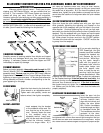
• Take the Bridge Mount and position it on the seat stay bridge,
centered and aligned with the seat stays.
• Insert one of the motor mount bolts through the bottom hole of the
Bridge Mount and finger-tighten it into the bottom hole of the
Threaded Plate.
MOUNTING MOTOR UNIT
• Slide the slot of the Hinge Bracket (attached to the ZAP Motor
Unit) around the Motor Mount Bolt, between the inside of the seat
stays and the Threaded Plate. Deflating the tire may be necessary
to get the motor in place.
• Finger tighten the remaining motor mount bolt through the Bridge
Mount, and into the Threaded Plate.
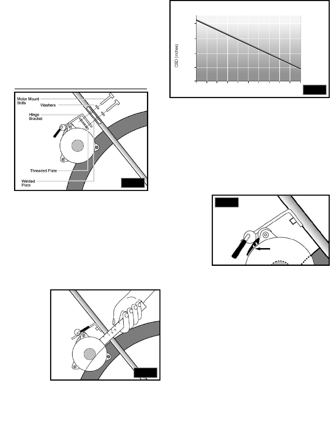
IF YOUR BIKE DOES HAVE THE WELDED PLATE, START HERE
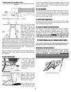
• Insert the motor mount bolts through two of the holes in the weld-
ed bridge plate and finger tighten into the two holes of the
Threaded Plate. (see Fig. 4)
• Slide the slot of the Hinge Bracket (attached to the ZAP Motor
Unit) around the Motor Mount Bolt, between the inside of the seat
stays and the Threaded Plate. Deflating the tire may be necessary
to get the motor in place.
4) Adjusting Motor Unit
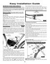
• With Cam Lever in the up (disengaged) position, adjust the ZAP
Motor Unit by sliding it up or down along the seat stays until the
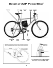
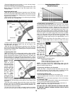
proper Critical Set-Up Distance (CSD) is achieved. The CSD is the
distance between the motor and the Seat Stays when the roller is
just touching the tire. (see Fig. 5). Determine the CSD for your bike
by referring to Fig. 6. The recommended pressure for your tires is
printed on the tires.
NOTE: In some
cases (on Cruiser
bikes in particular),
the Standoff (silver
member between
the two motors) will
hit the tire when
the Motor Unit is
pulled in against
the seat stays of
the bike. When
this happens,
adhere the remain-
ing piece of Cam
Ramp on the motor
where it contacts the seat stay. Then, readjust the motor, using the
space between the Seat Stay and the piece of Cam Ramp as the
new CSD.
• Once the CSD is attained, tighten the bolts using the 4mm Allen
Wrench (make sure the ZAP Motor Unit is centered around the tire
and the roller is flat on the tire as opposed to being slanted). Re-
check CSD and correct if needed.
• Put the Cam Lever in the down (engaged) position and notice
how far it forces the Roller into the tire. Ideally, the Cam will force
the Roller about 1/16” into the tire.
• If the Cam forces the roller into the tire more than 1/16”, remove
the Cam Ramp which is adhered to the motor under the Cam using
a flat-head screwdriver or pliers. Engage the Cam Lever, and
check to see if the Cam forces the Roller into the tire the desired
1/16” without a Cam Ramp. If the engagement is less than 1/16”,
take the spare Cam Ramp, which is shorter and slotted, and insert
it where the original Cam Ramp was removed. Check the engage
-
ment once again. If the Roller engagement into the tire is greater
than 1/16”, then snap off the end of the shorter Cam Ramp using
a flathead screwdriver or pliers and check the engagement. One
of these sizes of Cam Ramp will give you approximately 1/16” of
engagement.
• When the correct Cam Ramp size and position is found, cut a
piece of the Double-Sided Tape to match the inside of the Cam
Ramp.
• Peel off one
side of the tape
and adhere it to
the inside of
the Cam Ramp,
without touching
the tacky sur-
face (see Fig. 7).
• Peel off the
other side of the
tape and care-
fully adhere the
Cam Ramp to the motor, under the Cam butted up against the sil
-
ver Spacer Tube.
• Now recheck all critical dimensions:
-Critical Setup Distance
-Roller engagement into the tire when the Cam
Lever is in the down position (1/16”)
NOTE: If you have a bike with a welded bridge plate, you may
have to use different holes in the welded bridge plate (higher or
lower) to achieve proper set-up.
5) Connecting the Motor to the Controller
• Attach the motor / controller lead with the white dot to the motor
lead with the white dot. Plug the other motor / controller lead into
the remaining motor lead (the lead without the white dot.)
6) Connecting Battery Pack
• Push the battery pack assembly into the battery tray.
• Connect battery power connector to controller power connector
(black & red).
• Attach the Velcro on the battery bag flaps to Velcro on the battery
tray and make it tight.
• Run the battery strap underneath the battery tray and through the
“D” ring on the other battery flap and pull tight.
• Fasten the battery strap to itself with the velcro attached to it.
NOTE: Initially, tray is very tight around battery.
ZAP DEFLATES THE TIRES BEFORE PACKAGING THE BIKE
TO PREVENT DAMAGE DURING SHIPPING. INFLATE BOTH
TIRES TO 55 PSI.
Critical Setup Distance (CSD) for
Different Tire Pressures
1/2”
40 45 50 55 60 65 70 75 80 85 90
Tire Pressure (psi)
5/8”
11/16”
9/16”
3/4”
Double
Sided Tape
Fig.5
Fig.6
Fig.7
9
Fig.4


