


ASSEMBLY
Assembly requires two persons. Set the treadmill in a cleared area and remove all packing materials; do not
dispose of the packing materials until assembly is completed. Note: The underside of the treadmill walking
belt is coated with high-performance lubricant. During shipping, a small amount of lubricant may be transferred to
the top of the walking belt or the shipping carton. This does not affect treadmill performance. If there is lubricant
on top of the walking belt, simply wipe off the lubricant with a soft cloth and a mild, non-abrasive cleaner.
Assembly requires a phillips screwdriver and two adjustable wrenches .
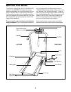
Note: To identify small parts used during assembly, refer
to the PART IDENTIFICATION CHART in the center of this
manual.
5
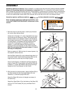
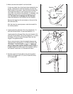
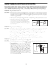
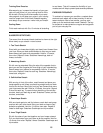
1. With the help of a second person, carefully tip the tread-
mill onto its right side as shown.
Identify the Left Upright (17), which does not have a large
round hole near the lower end. (Note: There may be iden-
tification decals on the Uprights.) Hold the Left Upright so
the indicated small hole is in the position shown, and hold
a Frame Spacer (13) between the Left Upright and the
Frame (55). Finger tighten a Frame Bolt (10) with a
Washer (11) and a Star Washer (69) through the Left
Upright and the Frame Spacer into the Frame as shown.
Note: Do not tighten the bolts used in steps 1, 2, and 4
until step 4 is completed.
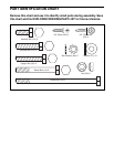
Refer to drawing 1b. With the help of a second person, tip
the treadmill onto its left side.
Hold the Right Upright (6) so the indicated large hole is in
the position shown. Insert the Wire Harness (22) into the
large hole and out of the top of the Right Upright.
Hold a Frame Spacer (13) between the Right Upright (6)
and the Frame (55). Finger tighten a Frame Bolt (10) with
a Washer (11) and a Star Washer (69) through the Right
Upright and the Frame Spacer into the Frame.
1a
1b
10
11
69
55
17
Large
Hole
Small
Hole
13
10
11
69
6
13
55
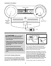
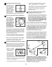
•Hazardous Voltage
•Risk of Electric Shock
•Unplug Treadmill before Assembly
/Disassembly.
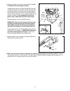
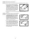
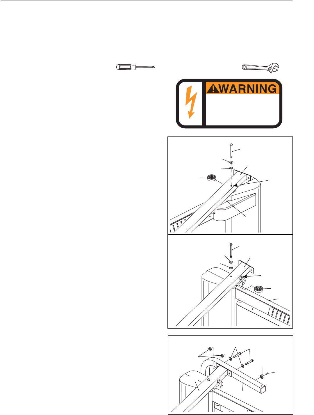
2. With the help of a second person, attach the Base (28) to
the Right Upright (6) with two Upright Bolts (30), two
Washers (11), and two Upright Nuts (29).
Attach the Base (28) to the Left Upright (not shown) in
the same way.
Attach four Base Pads (19) to the bottom of the Base (28)
with four 3/4” Tek Screws (24) (only one Base Pad is
shown).
2
30
24
19
11
29
6
28