


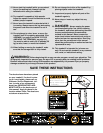
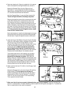
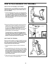
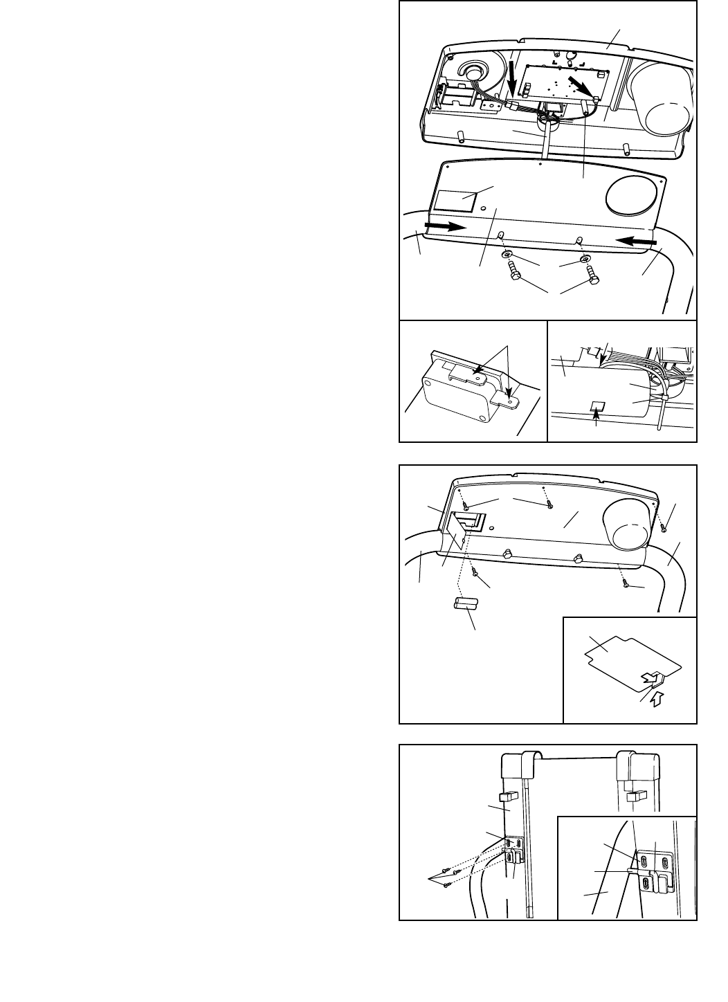
5. Insert the hinge of the Battery Cover (8) into the Console
Plate (4) in the location shown; the Battery Cover should
pivot on its hinge. Set the Console Base (1) on the
Console Plate. Make sure the Wire Harness (22) is clear
of the square battery access hole and the boss (see
drawing 4a above). Make sure that no wires will be
pinched before attaching the Console Base to the
Console Plate. Tighten five Screws (5) into the Console
Plate and the Console Base in the locations shown.
The console requires two "AA" batteries (not included).
Alkaline batteries are recommended. Touch the Left
Handrail (6) to discharge any static. Next, open the
Battery Cover (8). Press two batteries into the battery com-
partment, with the negative (–) ends of the batteries touch-
ing the springs. Close the battery cover, push up on the
tab, and then push the tab forward as shown in the inset
drawing. Make sure that the tab locks into place.
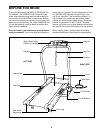
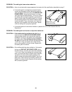
7. Make sure that all parts are properly tightened before you use the treadmill. Keep the included allen
wrench in a secure place. The allen wrench is used to adjust the walking belt (see page 13). To protect the
floor or carpet, place a mat under the treadmill.
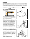
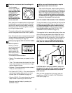
4. See inset drawing 4c. If there is a plastic tie in the square
hole in the bottom of the Right Handrail (6), remove it.
Attach the Console Plate (4) to the Right and Left
Handrails (6, 7) by pushing the Handrails inward and
tightening two Console Bolts (9) and Handrail Washers
(11) into the Console Plate and Handrails.
Hold the Console Base (1) near the Right Handrail (6).
Touch the Right Handrail to discharge any static.
Remove the tape from around the connectors at the end
of the Wire Harness (22). Locate the two wires in the
Wire Harness that have L-shaped connectors on the
ends. Press the connectors onto the two tabs on the red
switch indicated in inset drawing 4b. Connect the other
two wires in the Wire Harness to the back of the Console
Base (1) in the locations shown by the arrows in drawing
4a. If the connectors do not fit together easily, rotate
them and then connect them.
See inset drawing 4c. Loop the included plastic tie through
the square hole on the top and around the Wire Harness
(22) as shown. Tighten the plastic tie and cut off the end.
22
Boss
1
6
4
7
11
9
Square Hole
4a
5
4
5
Battery
Acess
7
1
6
5
5
5
Tab
Batteries
8
8
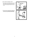
6. Make sure that the Latch Pin (69) is in the Storage Latch
(41) as shown.
Attach the Storage Latch (41) to the Frame (55) with the
three Screws (5). Do not tighten the Screws yet.
Position the Storage Latch so that the Latch Pin (69) is
aligned with the hole in the Left Handrail (7). Slide the
Latch Pin into the hole as shown in the inset drawing.
Then, tighten the three Screws.
41
55
5
6
41
Hole
69
7
69
Tie
Remove Tie
22
6
4c
4b
Tabs
6