


4
ASSEMBLY
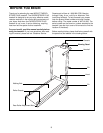
The help of a second person is recommended. Set the treadmill in a cleared area and remove all packing
materials. Do not dispose of the packing materials until assembly is completed. Assembly requires only the
included allen wrench and wrench .
38
13
13
37
37
38
Hole
Holes
Holes
1
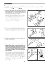
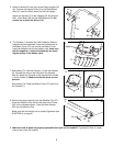
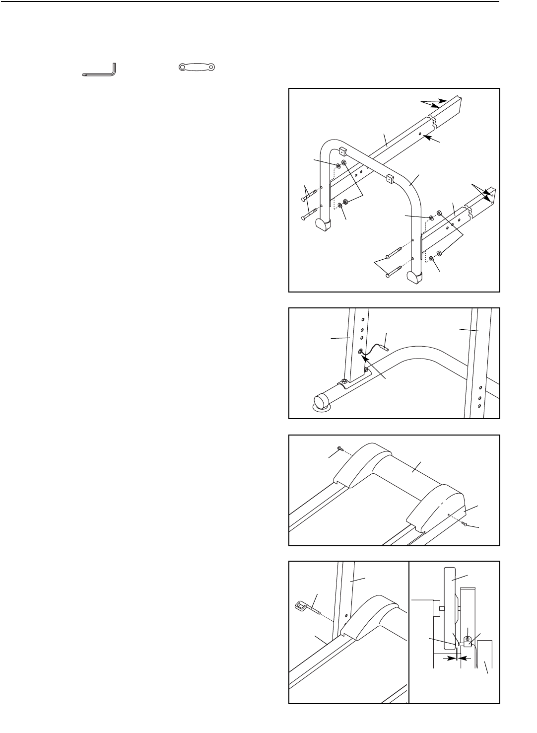
1. Identify the Right Upright (36), which has a single hole in
the indicated location. Hold the Right Upright against the
Base (14) as shown, and orient the Right Upright so the
two indicated holes are on the side shown.
Attach the Right Upright (36) to the Base (14) with two
M8 x 50mm Bolts (38), two M8 Curved Washers (37),
and two M8 Nylon Nuts (13) as shown.
Attach the Left Upright (35) to the Base (14) in the same
way. Make sure that the Left Upright is oriented so the
two indicated holes are on the side shown.
3. Attach the Hood (28) to the front of the Frame (29) with
two M5 x 10mm Bolts (10).
3
10
10
28
29
2. Raise the Left Upright (35) and the Right Upright (36) to
the position shown. Feed the Reed Switch Wire (6) into
the top of the Left Upright and out of the indicated hole.
2
6
Hole
35
36
36
35
14
37
37
4a
4. See drawing 4a. Hold the front of the Frame (29)
between the Left Upright (35) and the Right Upright (not
shown). Align the holes near the front of the Frame with
one of the three sets of adjustment holes in the Uprights.
Insert a Pin (4) into each Upright and each side of the
Frame. Make sure that the Pins are fully inserted at
the same height.
Look under the Frame (29) near the Left Upright (35).
See drawing 4b. Locate the Clip (11) attached to the
underside of the Frame. Insert the Reed Switch (6) into
the Clip as shown. Next, locate the Magnet (12) on the
left Flywheel (9). Turn the Flywheel until the Magnet is
aligned with the Reed Switch. Move the Reed Switch
so that there is a 1/8” gap between the Reed Switch
and the Magnet. Then, tighten the M4 x 12mm Screw
(3) in the Clip.
4
29
12
9
3
11
6
1/8”
View from
below
35
4b
29