


9
ELECTRONIC MONITOR TROUBLE-SHOOTING
If the console does not function properly, the batteries
should be replaced. To replace the batteries, see
assembly step 7 on page 8. In addition, make sure
that the console wire is connected to the extension
wire. See assembly step 6 on page 7.
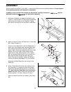
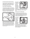
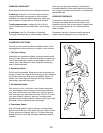
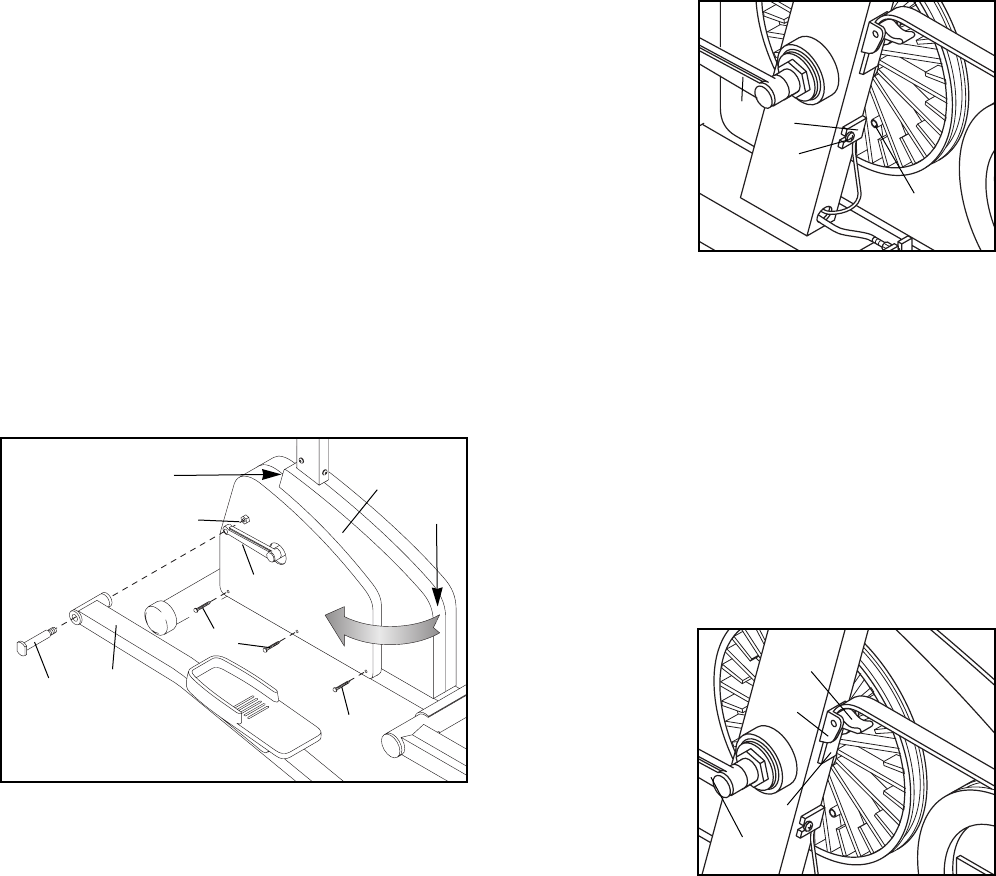
HOW TO ADJUST THE REED SWITCH
If the console does not display correct feedback, the
reed switch should be adjusted. In order to adjust the
reed switch, the Left Side Shield (5) must be removed.
Remove the 1/2Ó Nylon Locknut (37) from the Pedal
Bolt (36). Turn the Pedal Bolt and remove it from the
Crank (38); do not remove the Pedal Bolt from the
Left Pedal Arm (7). Set the Left Pedal Arm aside.
Remove the three M4 x 38mm Screws (66) from the
bottom of the Left Side Shield (5). Grasp both Side
Shields at the top and gently pull them apart. Make
sure that the arm of the Crank (38) is in the position
shown in the drawing above. Hold the Left Side Shield
at the rear and pull it gently away from the frame.
Work the Left Side Shield forward off the arm of the
Crank and remove it.
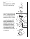
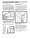
Next, locate the
Reed Switch (3).
Loosen, but do
not remove, the
M4 x 16mm
Screw (51).
Slide the Reed
Switch slightly
toward or away
from the magnet
on the pulley.
Retighten the
Screw. Turn the Crank (38) for a moment. Repeat until
the console displays correct feedback. When the Reed
Switch is correctly adjusted, reattach the left side
shield.
HOW TO ADJUST THE TENSION BELT
If the pedals do not have enough resistance, even
when the pedal resistance knob is turned to the maxi-
mum setting, the Resistance Belt (24) may need to be
adjusted. To adjust the Resistance Belt, the left side
shield must be removed. Refer to the instructions at
the left to remove the left side shield.
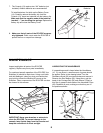
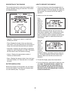
Next, turn the
pedal resistance
knob to its low-
est setting.
Locate and
open the latch
on the Resis-
tance Belt
Clamp (49).
Grip the end of
the Resistance
Belt (24) and
pull it down to remove any slack. While holding the
end of the Tension Belt, close the latch on the Tension
Belt Clamp. Turn the Crank (38) for a moment to
make sure that there is not too much resistance.
When the resistance strap is properly adjusted, reat-
tach the left side shield.
3
51
38
49
Latch
24
38
Magnet
36
7
5
66
38
Rear
Top
37
66