


11
Inspect and tighten all parts of the elliptical crosstrainer
regularly. Replace any worn parts immediately.
To clean the elliptical crosstrainer, use a damp cloth
and a small amount of mild soap. Important: Keep
liquids away from the console, place only a sealed
water bottle in the water bottle holder, and keep
the console out of direct sunlight. During storage,
remove the batteries from the console.
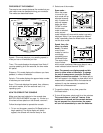
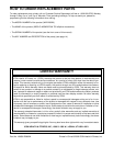
BATTERY REPLACEMENT
If the console display becomes dim, the batteries
should be replaced; most console problems are the
result of low batteries. To replace the batteries, refer
to step 4 on page 6 and remove the console from the
upright. Next, refer to step 3 on page 6 and insert
three batteries into the console. Reattach the console
to the upright, being careful not to pinch the wires.
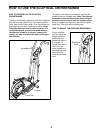
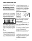
HOW TO ADJUST THE REED SWITCH
If the console does not display correct feedback, the
reed switch should be adjusted. To adjust the reed
switch, you must remove the Left Pedal Arm (11) and
the Left Side Shield (3).
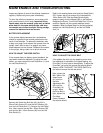
Remove the Pedal Arm Bolt Set (40), the M10 x
25mm Patch Screw (22), and the M10 Washer (35)
from the Left Pedal Arm (11). Remove the Left Pedal
Arm. Next, remove the two M4 x 25mm Screws (56)
and the four M4 x 16mm Screws (42) from the Left
Side Shield (3).
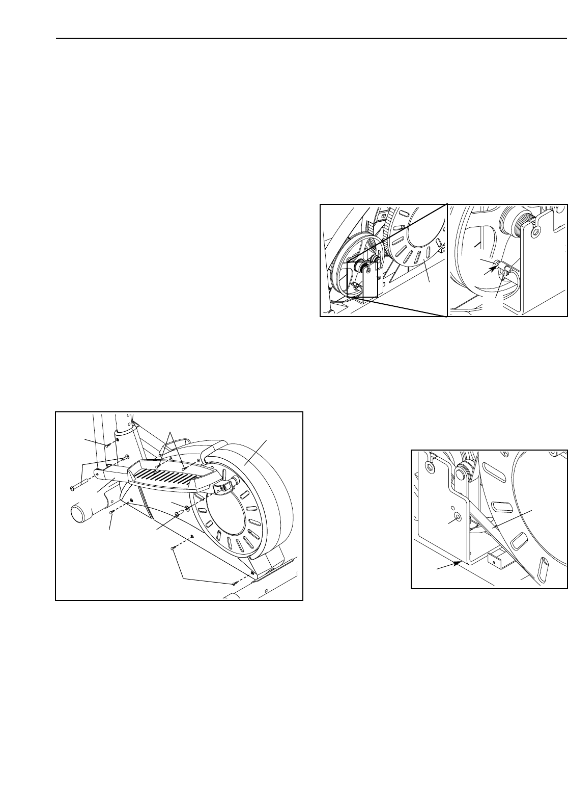
Refer to the drawing below and locate the Reed Switch
(53). Loosen, but do not remove, the indicated M4 x
16mm Screw (42). Slide the Reed Switch slightly
toward or away from the Magnet (58) on the flywheel.
Retighten the Screw. Turn the left Pedal Disc (15) for a
moment. Repeat until the console displays correct
feedback. When the Reed Switch is correctly adjusted,
reattach the Left Side Shield (3) and the Left Pedal
Arm (11).
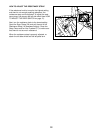
HOW TO ADJUST THE DRIVE BELT
If the pedals slip while you are pedaling, even when
the resistance is adjusted to the highest setting, the
Drive Belt (19) may need to be adjusted. To adjust the
Drive Belt, you must first remove the left side shield.
Refer to HOW TO ADJUST THE REED SWITCH at
the left and remove the left side shield.
Next, loosen the
M8 x 22mm Flat
Head Screw
(41) and turn
the Idler
Adjustment Bolt
(62) until the
Drive Belt (19)
is tight. When
the Drive Belt is
tight, tighten the
Flat Head
Screw. Reattach
the left side shield.
MAINTENANCE AND TROUBLESHOOTING
42
56
42
42
22
35
3
40
15
41
62
19
11
58
53
42