


ASSEMBLY
Assembly requires two persons. Set the treadmill in a cleared area and remove all packing materials. Do not
dispose of the packing materials until assembly is completed. Note: The underside of the treadmill walking belt is
coated with high-performance lubricant. During shipping, a small amount of lubricant may be transferred to the
top of the walking belt or the shipping carton. This is a normal condition and does not affect treadmill perfor-
mance. If there is lubricant on top of the walking belt, simply wipe off the lubricant with a soft cloth and a mild,
non-abrasive cleaner.
Assembly requires the included hex keys and your own phillips screwdriver , wire cutters
and needlenose pliers .
For help identifying the assembly hardware, refer to the PART IDENTIFICATION CHART in the centre of
this manual. Note: The assembly hardware and other small parts are packaged in separate part bags. Do
not open the part bags until instructed to do so.
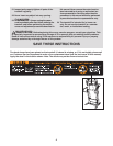
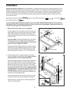
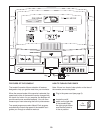
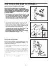
1. Make sure that the power cord is unplugged.
Place the Base (79) in the position shown, with the indi-
cated small holes on top (only one small hole is shown).
Place a Wheel (63) in each Wheel Housing (62), and
slide the Wheel Housings onto the ends of the Base that
have bolt holes.
Open part bag A. Attach the Wheels (63) to the Wheel
Housings (62) with 2 1/2” Bolts (61) and Wheel Nuts
(64). Make sure that the Wheel Nuts are on the sides
shown; do not overtighten the Bolts.
Slide the two Base Endcaps (75) onto the other ends of
the Base (79) (only one Base Endcap is shown). Attach
the four Base Pads (73) to the Base Endcaps and the
Wheel Housings (62) with four 1 1/4” Tek Screws (60).
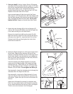
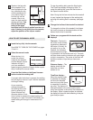
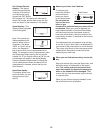
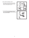
2. Raise the Base (79) to a vertical position, and hold it
near the treadmill Frame (96) as shown. Make sure that
the Wheels (63) are in the indicated position.
Identify the Right Upright (104), which has a large round
hole in the indicated location. Feed the Wire Harness
(65) into the hole and out of the top of the Right Upright.
Make sure that there are two U-Nuts (74) in the lower
end of the Right Upright (see drawing 2a). Hold
the Right
Upright against the Base (79) as shown.
Make sure that
the Right Upright is oriented so the pivot hole is in the
position shown. Hand tighten two 3” Bolts (58) with two
5/16” Star Washers (57) into the bottom of the Base and
the lower end of the Right Upright.
Attach the Left Upright (47) to the Base (79) in the same
way. Note: There is not a wire harness on the left side.
With the help of a second person, raise the Uprights (47,
104) to a vertical position.
60
73
Small Hole
75
61
73
63
62
Bolt
Hole
64
79
60
63
60
1
Pivot
Holes
79
63
63
58
57
47
58
57
65
2a
74
104
6
104
2
61
64
62
73
96
Round
Hole