


ASSEMBLY
The help of a second person is recommended. Set the treadmill in a cleared area and remove all packing
materials. Do not dispose of the packing materials until assembly is completed. Assembly requires only the
included hex key and wrench .
38
13
13
13
37
37
38
Holes
Bracket
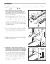
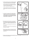
1. Identify the Right Upright (36); the Resistance
Control/Cable (44) is routed through the Right Upright.
Place the Base (14) near the Right Upright and the
Frame (29). Have another person hold the Right Upright
against the Base as shown.
Attach the Right Upright (36) to the Base (14) with two
M8 x 63mm Bolts (38), two M8 Curved Washers (37),
and two M8 Nylon Nuts (13) as shown. Make sure that
the Curved Washers are turned so they conform to the
curve of the Base.
Do not tighten the Nylon Nuts yet.
Attach the Left Upright (35) to the Base (14) in the same
way. Make sure that the Left Upright is oriented so the
two indicated holes are on the side shown.
Do not tight-
en the Nylon Nuts yet.
1
36
35
14
44
37
37
3a
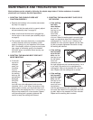
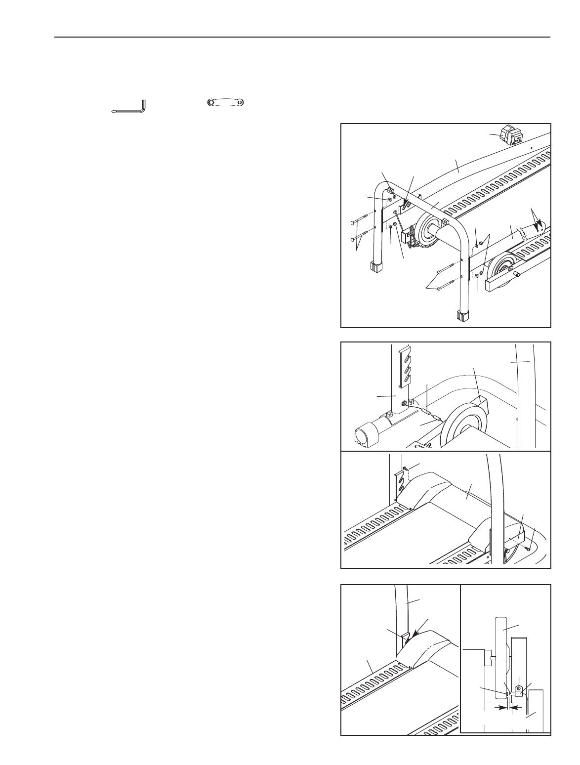
3. See drawing 3a. Locate the small incline knob on each
side of the Frame. Slide the knobs into one of the three
sets of slots in the brackets on the Uprights. Make sure
that the knobs are fully inserted at the same height.
Look under the Frame (29) near the Left Upright (35).
See drawing 3b. Locate the Clip (11) attached to the
underside of the Frame. Insert the Reed Switch (6) into
the Clip as shown. Next, locate the Magnet (12) on the
left Flywheel (9). Turn the Flywheel until the Magnet is
aligned with the Reed Switch.
Move the Reed Switch
so that there is a 3 mm (1/8 in.) gap between the
Reed Switch and the Magnet. Then, tighten the M4 x
12mm Screw (3) in the Clip.
Bracket
Knob
29
12
9
3
11
6
3 mm
V
iew from
beneath
35
3b
29
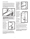
2a.Raise the Left Upright (35) and the Right Upright (36) to
the position shown. Place the front of the Frame (29)
between the Left Upright and the Right Upright. Connect
the Reed Switch Wire (6) to the Short Reed Switch Wire
(A).
2b.Attach the Hood (28) to the front of the Frame (29) with
two M5 x 10mm Bolts (10).
2a
35
36
29
2b
10
10
6
A
28
29
4