


MAINTENANCE AND TROUBLESHOOTING
Inspect and tighten all parts of the exercise cycle reg-
ularly. Replace any worn parts immediately.
To clean the exercise cycle, use a damp cloth and a
small amount of mild detergent. Important: To avoid
damage to the console, keep liquids away from
the console and keep the console out of direct
sunlight.
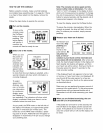
BATTERY REPLACEMENT
If the console display becomes dim, the batteries
should be replaced; most console problems are the
result of low batteries. To replace the batteries, see
assembly step 7 on page 6.
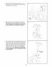
HOW TO ADJUST THE REED SWITCH
If the console does not display correct feedback, the
reed switch should be adjusted. To adjust the reed
switch, the left pedal, the upright covers, and the left
side shield must be removed.
Using an adjustable wrench, turn the left pedal clock-
wise and remove it. Next, remove the screws from the
upright covers and the left side shield. Note: One
screw from the side shield is shorter than the other
screws. Make sure to note the correct location of the
short screw. Then, carefully remove the upright covers
and the left side shield.
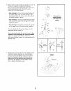
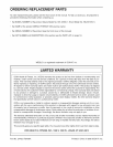
Next, turn the resistance knob to the lowest setting.
With the left side shield removed, locate the Reed
Switch (43). Turn the Crank (21) until the Magnet (38)
is aligned with the Reed Switch. Loosen, but do not
remove, the M4 x 15mm Screw (47). Slide the Reed
Switch slightly closer to or away from the Magnet, and
then retighten the Screw. Turn the Crank for a
moment. Repeat until the console displays correct
feedback. When the Reed Switch is correctly adjust-
ed, reattach the left side shield, the upright covers,
and the left pedal.
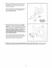
HOW TO ADJUST THE BELT
If you can feel the pedals slip while you are pedaling,
even when the resistance is at the highest level, the
belt may need to be adjusted. See HOW TO ADJUST
THE REED SWITCH at the left and remove the left
pedal, the upright covers, and the left side shield.
To adjust the belt, you must also remove the right
pedal and the right side shield. Using an adjustable
wrench, turn the right pedal counterclockwise and
remove it. Then, remove the screws from the right
side shield. Note: One screw from the side shield is
shorter than the other screws. Make sure to note the
correct location of the short screw. Then, carefully
remove the right side shield.
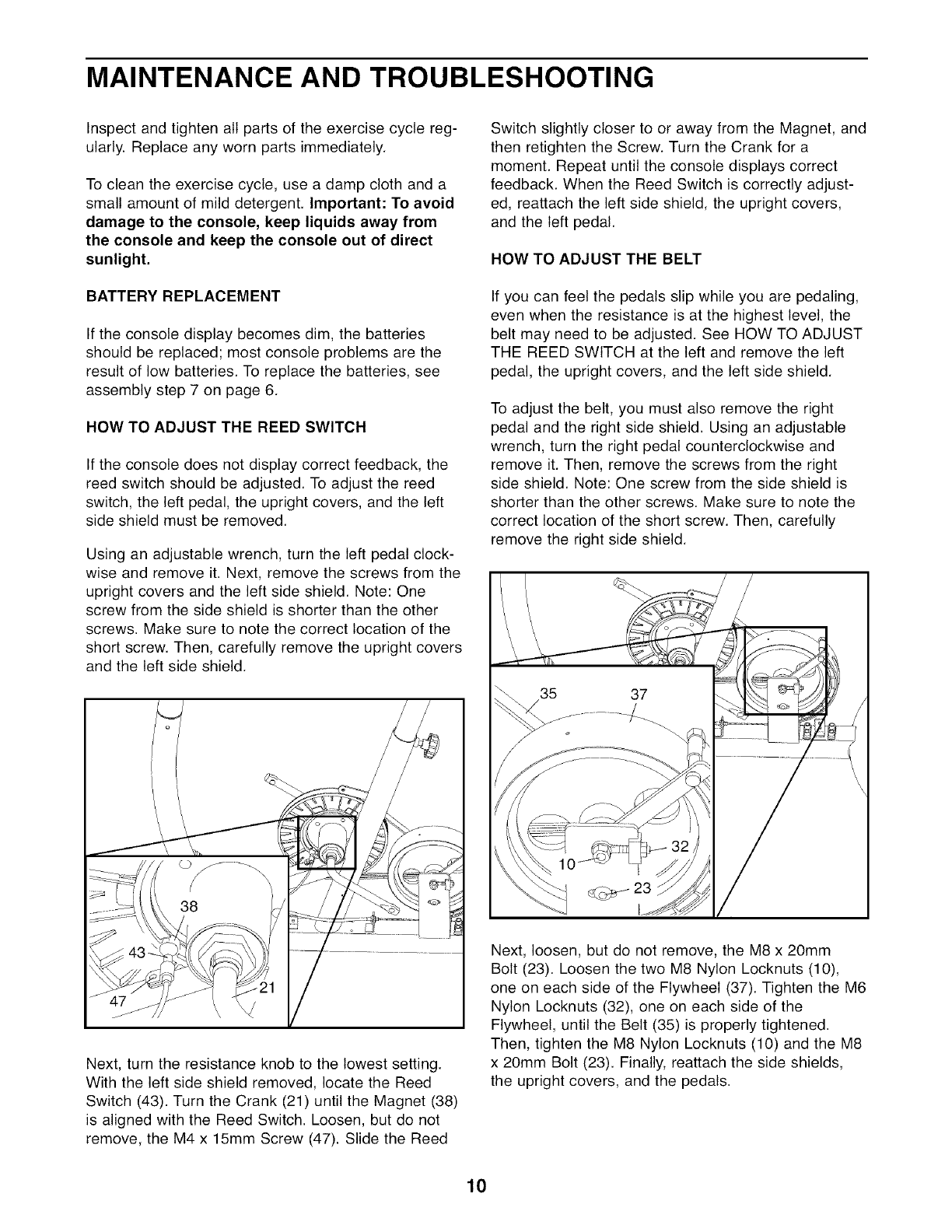
Next, loosen, but do not remove, the M8 x 20mm
Bolt (23). Loosen the two M8 Nylon Locknuts (10),
one on each side of the Flywheel (37). Tighten the M6
Nylon Locknuts (32), one on each side of the
Flywheel, until the Belt (35) is properly tightened.
Then, tighten the M8 Nylon Locknuts (10) and the M8
x 20mm Bolt (23). Finally, reattach the side shields,
the upright covers, and the pedals.
10