


8
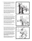
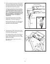
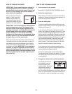
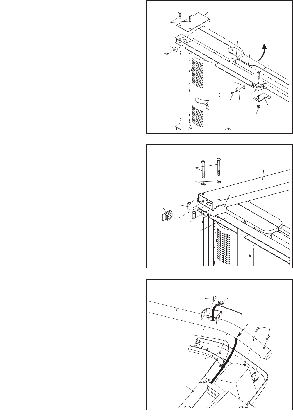
7. Set the Console (87) face down on a soft sur-
face to avoid scratching the Console. Identify the
Right Handrail (90), which has a large hole in the
location shown. Hold the Right Handrail near the
Console. Attach the console ground wire to the
Right Handrail with a #8 x 1/2" Screw (22).
Next, insert the console wire into the large hole
in the Right Handrail (90) and out of the top as
shown. Attach the Right Handrail with three
M4.2 x 19mm Screws (1). Make sure that no
wires are pinched. Start all three Screws be-
fore tightening any of them; do not over-
tighten the Screws.
Attach the Left Handrail (not shown) to the
Console (87) in the same way. Note: There are
no wires on the left side of the Console.
90
7
87
1
1
Large
Hole
Console
Wire
22
Console
Ground Wire
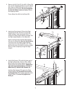
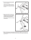
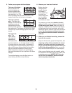
6. Press a Base Cap (82) into the Base (85).
Hold a Bolt Spacer (79) inside the lower end of
the Left Upright (73). Insert an M10 x 96mm Bolt
(5) with an M10 Star Washer (8) into the Left
Upright and the Bolt Spacer. Repeat this step
with a second Bolt Spacer (79), M10 x 96mm
Bolt (5), and M10 Star Washer (8).
Orient the Left Upright (73) and the Left Upright
Spacer (83) as shown. Hold the Left Upright
Spacer and the Left Upright against the Base
(85). Partially tighten the M10 x 96mm Bolts (5);
do not fully tighten the Bolts yet.
With the help of a second person, tip the tread-
mill so that the Base (85) is flat on the floor.
83
73
5
85
79
79
82
8
6
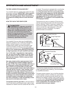
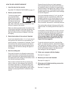
5. With the help of a second person, carefully tip
the treadmill onto its right side. Partially fold the
Frame (48) so the treadmill is more stable; do
n
ot fully fold the Frame yet.
R
emove and discard the two indicated bolts (A)
and the shipping bracket (B).
Attach a Base Foot (81) to the Base (85) in the lo-
cation shown with a Base Foot Spacer (104) and
an M4.2 x 25mm Tek Screw (2). Then, attach an-
other Base Foot (81) with only a Tek Screw (2).
Remove the M10 Nut (33), the M10 x 50mm
Bolt (27), and the shipping bracket (C) from the
Base (85). Attach a Wheel (86) with the Bolt and
the Nut that you just removed. Do not over-
tighten the Nut; the Wheel must turn freely.
Discard the shipping bracket.
5
85
86
48
27
33
C
81
2
81
104
2
B
A