


5
1
56
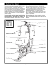
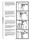
High Side of
Bracket
3
5
51
51
14
1
4
1
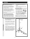
Before beginning assembly, carefully read the
following information and instructions:
¥ Place all parts of the home gym system in a
cleared area and remove the packing materials;
do not dispose of the packing materials until
assembly is completed.
¥ The assembly is divided into four stages: 1)
frame assembly, 2) press and butterfly arm
assembly, 3) cable and pulley assembly, and 4)
seat and backrest assembly. The hardware for
each stage is packaged separately.
¥ Wait until you begin each assembly stage to open
that parts bag.
¥ For help identifying the small parts used in
assembly, use the PART IDENTIFICATION
CHART located in the center of this manual.
Note: Some small parts may have been pre-
attached for shipping. If a part is not in the parts
bag, check to see if it has been pre-attached.
¥ As you assemble the home gym system, be sure
that all parts are oriented as shown in the
drawings.
¥ Tighten all parts as you assemble them, unless
instructed to do otherwise.
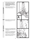
THE FOLLOWING TOOLS (NOT INCLUDED) ARE
REQUIRED FOR ASSEMBLY:
¥ Two (2) adjustable wrenches
¥ One (1) standard screwdriver
¥ One (1) phillips screwdriver
¥ One (1) rubber mallet
¥ Lubricant, such as grease or petroleum jelly,
and soapy water will also be needed.
Assembly will be more convenient if you have the
following tools: A socket set, a set of open-end or
closed-end wrenches, or a set of ratchet wrenches.
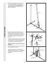
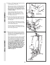
1. Before beginning assembly, be sure that
you have read and understand the infor-
mation in the box above.
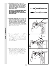
Press a 2Ó Square Outer Cap (51) onto each
end of the Stabilizer (5). Press a 2Ó Square
Inner Cap (27) into the end of the Base (4).
Insert two 5/16Ó x 2 3/4Ó Carriage Bolts (14)
up through the Stabilizer (5). Insert four
5/16Ó x 2 1/2Ó Carriage Bolts (1) up through
the Base (4).
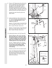
Slide the indicated end of the Base (4) onto
the 5/16Ó x 2 3/4Ó Carriage Bolts (14) in the
Stabilizer (5). Slide the Rear Upright (56)
onto the Carriage Bolts. Hand tighten a 5/16Ó
Nylon Locknut (3) onto each Carriage Bolt.
The high side of the bracket on the Rear
Upright must be on the side shown. Do
not tighten the Nylon Locknuts yet.
FRAME ASSEMBLY
27
Assembly