


8 9
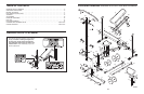
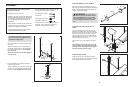
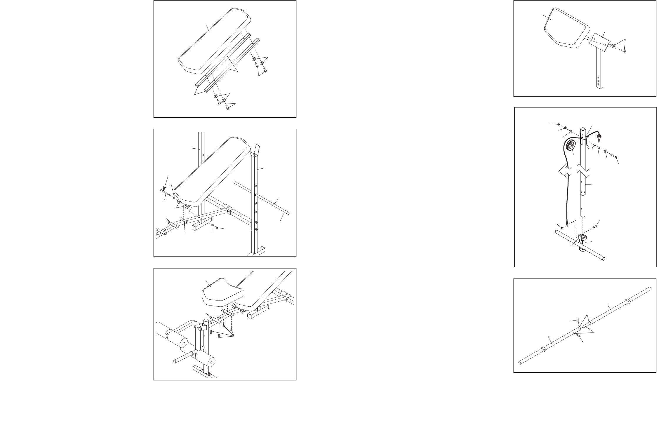
10. Attach the Curl Pad (45) to the Curl Post (27) with
two M6 x 16mm Screws (29).
10
45
27
29
11
48
14
12
33
12. Insert the Inner Bar (43) into the Outer Bar (40)
and align the indicated holes. Using a hammer,
tap the two Roll Pins (41) into the holes until they
are flush with the Outer Bar.
12
43
40
41
41
Holes
Holes
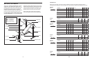
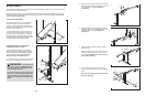
7. Orient the Backrest Tubes (5) and the Backrest
(6) as shown.
A
ttach the Backrest Tubes (5) to the Backrest (6)
with four M6 x 38mm Screws (30) and four M6
W
ashers (26); do not tighten the Screws yet.
8. Insert the Backrest Support (7) into a set of holes
in the Uprights (1). Rotate the Backrest Support to
the locked position, with the locking pin wrapped
around the left Upright.
Apply grease to an M10 x 137mm Bolt (36).
Attach the Backrest Tubes (5) to the welded tube
on the Frame (2) with the M10 x 137mm Bolt (36),
two M10 Washers (34), and an M10 Locknut (33).
Do not overtighten the Locknut; the Backrest
Tubes must pivot easily.
See steps 1–4. Tighten the M8 Locknuts (17).
See step 7. Tighten the M6 x 38mm Screws (30).
9. Attach the Seat (11) to the Frame (2) with four M6
x 16mm Screws (29).
7
5
30
2
6
26
30
6
8
Grease
34
5
36
7
1
2
Welded
Tube
1
Locking
Pin
33
34
9
11
29
2
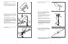
11. Route the Cable (19) through the Lat Tower (14)
and over the Pulley (25). Make sure that the
Cable is under the lat bar rest.
Attach the Pulley (25) inside the Lat Tower (14)
with an M10 x 50mm Bolt (47), two M10 Washers
(34), two Pulley Spacers (49), and an M10
Locknut (33).
Next, insert an M10 x 20mm Bolt (48) into the
bracket on the Weight Carriage (12) from the side
shown.
Slide the Weight Carriage (12) onto the Lat Tower
(14). Make sure that the bracket on the Weight
Carriage and the lat bar rest on the Lat Tower
are on opposite sides of the Lat Tower. Attach
the Cable (19) to the M10 x 20mm Bolt (48) with
an M10 Locknut (33).
49
34
25
47
34
33
49
19
Lat Bar
Rest
Bracket
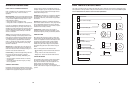
13. Make sure that all parts are properly tightened before the weight bench is used. Note: Some hardware
may be left over after assembly is completed. The use of all remaining parts will be explained in
ADJUSTMENT, starting on page 10.
Holes