7
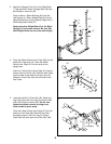
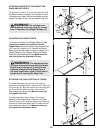
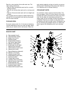
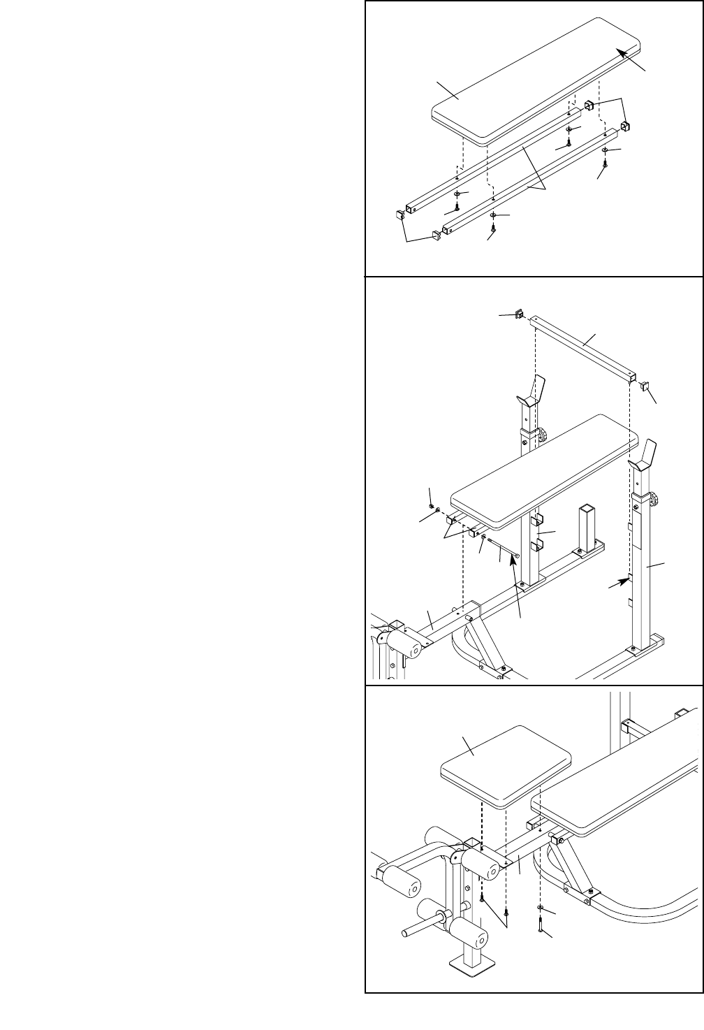
7. Press two 25mm Square Inner Caps (39) into the
Adjustment Tube (37). With the pins on the
Adjustment Tube facing downward, slide the
Adjustment Tube into a set of adjustment brack-
ets on the Uprights (4, 5).
Lubricate an M10 x 168mm Bolt (40). Attach the
Backrest Tubes (20) to the Bench Frame (1) with
the Bolt, two M10 Washers (29), and an M10
Nylon Locknut (45). Do not overtighten the
Nylon Locknut; the Backrest Tubes must be
able to pivot freely.
Tighten the M8 Nylon Locknuts (43) used in
step 2, and the four M6 x 38mm Screws (14)
used in step 6.
7
39
39
45
29
29
40
37
20
Bracket
Lubricate
4
5
1
6
20
14
14
14
14
15
Narrow
End
31
31
31
31
39
39
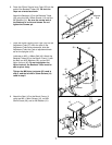
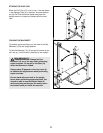
6. Press four 25mm Square Inner Caps (39) into the
ends of the Backrest Tubes (20). Be sure the
Caps are oriented as shown.
Attach the Backrest (15) to the Backrest Tubes
(20) using four M6 x 38mm Screws (14) and four
M6 Washers (31). Be sure the narrow end of
the Backrest is on the end shown. Do not
tighten the Screws yet.
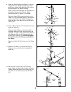
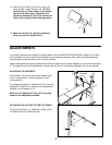
8. Attach the Seat (16) to the Bench Frame (1)
using two M6 x 16mm Screws (10), an M6 x
50mm Screw (38), and an M6 Washer (31).
8
38
31
16
10
1


