


5
Before beginning assembly, carefully read the
following information and instructions:
• Assembly requires two people.
• Place all parts in a cleared area and remove the
packing materials. Do not dispose of the packing
materials until assembly is completed.
• Tighten all parts as you assemble them, unless
instructed to do otherwise.
• As you assemble the weight system, make sure
all parts are oriented as shown in the drawings.
• For help identifying small parts, use the P
ART
IDENTIFICATION CHART.
The following tools (not included) are required
for assembly:
• two adjustable wrenches
• one rubber mallet
• one standard screwdriver
• one Phillips screwdriver
• lubricant, such as grease or petroleum jelly,
and soapy water.
Assembly will be more convenient if you have a
socket set, a set of open-end or closed-end
wrenches, or a set of ratchet wrenches.
Make Things Easier for Yourself
Everything in this manual is designed to ensure
that the weight system can be assembled suc-
cessfully by anyone. However, it is important to
realize that the versatile weight system has
many parts and that the assembly process will
take time. Most people find that by setting aside
plenty of time, assembly will go smoothly.
ASSEMBLY
1
28
28
77
75
77
75
77
75
1
2
3
28
74
29
29
71
Indents
57
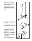
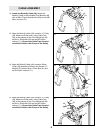
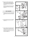
1. Before beginning assembly, be sure that you
have read and understand the information in
the box above.
Press two 50mm x 75mm Inner Caps (29) into
the sides of the Foot Plate (74).
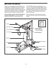
Orient the Rear Base (3) with the indents around
the holes on the bottom. Attach the Front Base
(1) and the Rear Base to the Center Base (2) with
two M10 x 70mm Bolts (58) and two M10 Nylon
Locknuts (71).
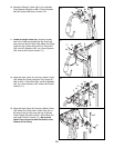
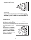
FRAME ASSEMBLY
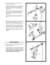
2. Insert six M10 x 65mm Carriage Bolts (57) up
through the Front and Rear Bases (1, 3).
Press the three Base Caps (28) onto the ends of
the Front Base (1), the Center Base (2), and the
Rear Base. Secure the Base Caps with three M4
x 20mm Screws (77) and three M5 Washers (75).
Attach the Foot Plate (74) to the Center Base (2)
with two M10 x 65mm Carriage Bolts (57) and
two M10 Nylon Locknuts (71).
2
1
2
3
57
57
58
58
57
71
71