


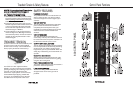
ASSEMBLY
TRUE treadmills are shipped in two pieces:
the pedestal assembly (which includes the
control console) and the base.
Instructions for assembling the unit:
1. Remove the protective packaging
materials.
NNOOTTEE::
Do not lift the treadmill
by the motor when removing from carton!
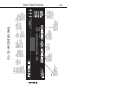
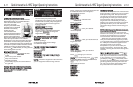
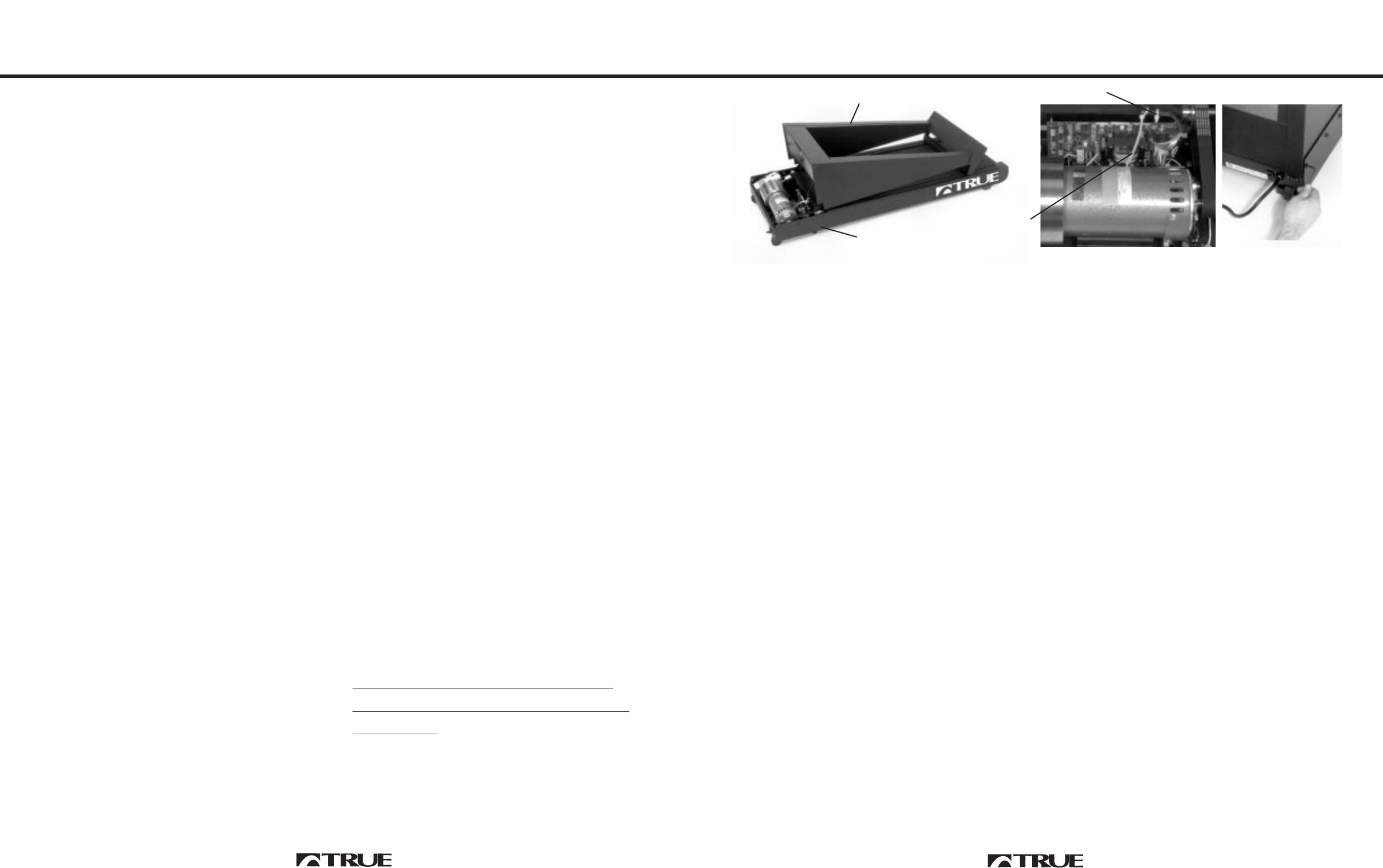
2. Lay pedestal on deck as shown. (Fig. 1)
3. Feed wire harness through reusable wire
ties from left to right. (Fig. 2)
4. Tighten wire ties and tuck excess tie down
between motor and PWM board. (Fig.2)
NNOOTTEE::
Do not cut off excess wire tie.
These are reusable.
5. Raise top of pedestal into place.
6. Install three of the enclosed screws with lock
washers on each side, then tighten all six
screws. (Fig. 3)
PARTS INCLUDED:
11 -- AALLLLEENN WWRREENNCCHH
66 -- SSCCRREEWWSS
66 -- SSTTAARR WWAASSHHEERRSS ((LLOOCCKK WWAASSHHEERRSS))
11 -- OOWWNNEERRSS MMAANNUUAALL
11 -- WWAARRRRAANNTTYY CCAARRDD
11 -- HHEEAARRTT RRAATTEE TTRRAANNSSMMIITTTTEERR WWIITTHH
SSTTRRAAPP ((HHRRCC MMOODDEELLSS OONNLLYY))
IIMMPPOORRTTAANNTT::
Do not operate unless all six
screws are fastened securely. Be sure
screws and lock washers thread into the
holes in pedestal. Reverse procedure
whenever removing the pedestal. Remove
pedestal console only while treadmill is at
zero grade and unplugged.
EELLEECCTTRRIICCAALL RREEQQUUIIRREEMMEENNTT
:
Your TRUE treadmill requires
aa ddeeddiiccaatteedd
112200 VVAACC 2200 aammpp ggrroouunnddeedd oouuttlleett cciirrccuuiitt..
WWAARRNNIINNGG::
Do not use an extension cord or
an ungrounded outlet. The ground helps
prevent electrical damage to your treadmill and
enhances your safety by preventing shock.
This grounded outlet is critical for the HRC
system to function properly.
NNOOTTEE::
Units
produced for use outside of the U.S.A. will have
voltage indicated on the identification tag.
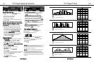
BELT ADJUSTMENTS
Your treadmill’s running belt has been
properly aligned at the factory. However,
when the treadmill is used on an uneven
surface, please follow these instructions:
PPRREEFFEERRRREEDD MMEETTHHOODD
Level the treadmill by placing shims 1/8” to
3/8” thick under the front wheel and rear
shock absorber on one side.
NNOOTTEE::
This
method will provide extended belt life by
keeping both rollers parallel. Adjusting the
belt tracking by using the roller bolts will
cause the belt to stretch on one side.
Assembly & Belt Adjustment
1-4
Learning The Basics
1-3
SETTING UP YOUR
TREADMILL
Place your treadmill on a clean, level surface.
Make sure the electrical cord easily reaches a
grounded three-pronged outlet and has
enough slack to allow the deck to incline
unhindered by the cord. Do not allow the
treadmill assembly to rest on the cord.
Although your treadmill is designed to
operate on most carpeted surfaces, some
deeply padded or heavy shag carpets can
cause damage to the unit. To prevent
damage to your treadmill or carpet, have
someone stand on the deck and make sure
the treadmill belt doesn’t touch the carpet at
any point.
Your TRUE treadmill is designed for indoor
use only. Always keep the control panel out of
direct sunlight.
IMPORTANT ELECTRICAL
REQUIREMENTS
Your True treadmill requires a
ddeeddiiccaatteedd
120 VAC 20 amp grounded outlet circuit.
WWAARRNNIINNGG:: DDoo nnoott uussee aann eexxtteennssiioonn ccoorrdd oorr
aann uunnggrroouunnddeedd oouuttlleett.. TThhee ggrroouunndd hheellppss
pprreevveenntt eelleeccttrriiccaall ddaammaaggee ttoo yyoouurr ttrreeaaddmmiillll
aanndd eennhhaanncceess yyoouurr ssaaffeettyy bbyy pprreevveennttiinngg
sshhoocckk..
AA GGRROOUUNNDDEEDD OOUUTTLLEETT IISS CCRRIITTIICCAALL
FFOORR TTHHEE HHRRCC SSYYSSTTEEMM TTOO FFUUNNCCTTIIOONN
PPRROOPPEERRLLYY..
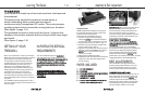
TTHHEE BBAASSIICCSS
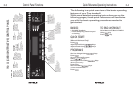
Your treadmill is made up of two main sections: the base and
the pedestal.
The base of the treadmill consists of a metal frame, a
shock-absorbing deck system and a powerful
continuous-duty horsepower DC motor. The motor powers
a pulley system which moves the running belt over the deck.
(See figure 1, page 1-4)
The pedestal mounts on the top of the frame. It places the
displays, information readout and touch keys within easy sight
and reach.
(See figure 1, page 1-4)
Fig. 1
Fig. 3
Fig. 2
PEDESTAL
BASE
1
2