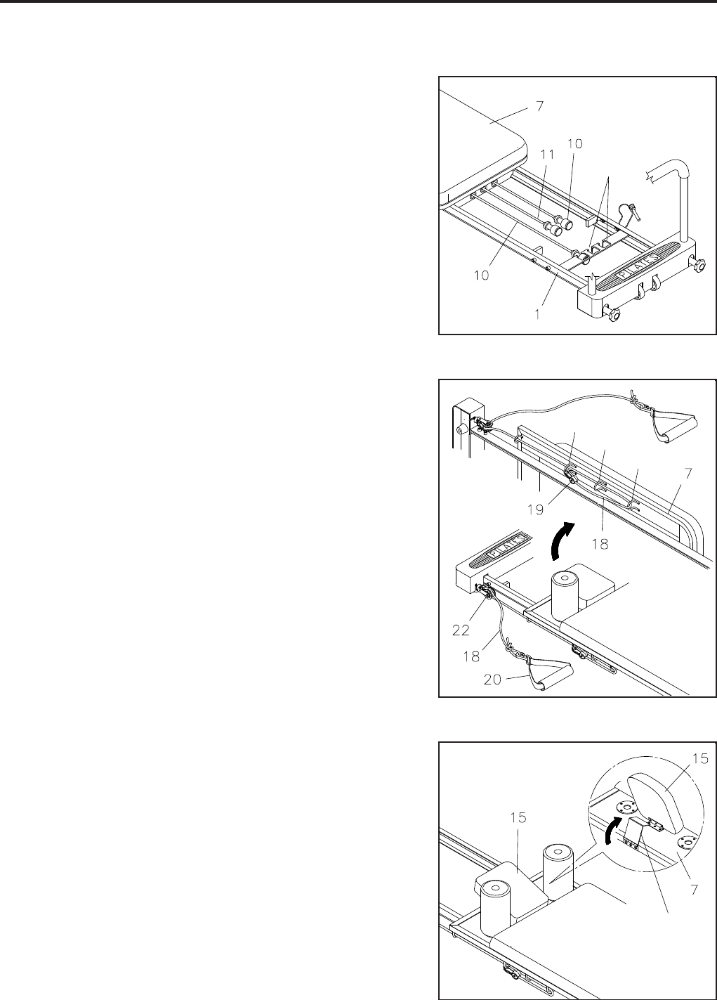
LOAD ADJUSTMENT
There are two TENSION CORDS(10) and one heavier RED
POWER CORD(11).
The resistance of the CARRIAGE(7) can be adjusted by
securing the TENSION CORDS(10, 11) in the slots located
on the FRONT FRAME(1). You can achieve various levels of
resistance by securing different numbers of the TENSION
CORDS(10, 11) in the slots.
NOTE:
OPERATIONAL INSTRUCTIONS
10
An extra RED POWER CORD(11) is included for
additional resistance. Replace one of the black
TENSION CORDS(10) with the RED POWER
CORD(11) if additional resistance is desired.
To achieve greater resistance in the RED POWER
CORD(11) and TENSION CORDS(10), stretch and
re-tie the tension cords in a more taut position.
ROPE LENGTH ADJUSTMENT
The ROPES(18) are wrapped on the HOOKS located on both
sides of the CARRIAGE(7). You can adjust the length between
the PULLEY SET(22) and the HAND STRAP(20) by attaching
the PLASTIC HOOKS(19) onto different HOOKS.
Arm Function: To position the HAND STRAP(20) close
to the PULLEY SET(22), hook the PLASTIC HOOK(19)
onto the HOOKS which will shorten the ROPE(18).
Leg Function: To achieve a full range of movement, hook
the PLASTIC HOOK(19) of the rope onto the desired A,
B, or C hook.
1.
2.
A
B
C
HEAD REST ADJUSTMENT
The HEAD REST(15) on the CARRIAGE(7) can be positioned
at an incline by simply pivoting the SUPPORT BRACKET
underneath the HEAD REST(15).
SUPPORT
BRACKET
SLOTS
1.
2.


