


EL3 /EL5 Elliptical
11
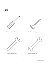
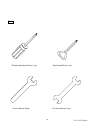
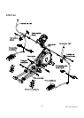
UNPACKING THE UNIT
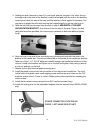
1. Using a razor knife (Box Cutter) cut the outside, bottom, edge of box along the dotted Line. Lift
Box over the unit and unpack.
2. Carefully remove all parts from carton and inspect for any damage or missing parts. If damaged
parts are found, or parts are missing, contact your dealer immediately.
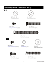
3. Locate the hardware package. The hardware is separated into steps. Remove the tools first.
Remove the hardware for each step as needed to avoid confusion.
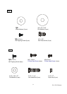
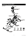
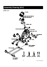
STEP 1: REAR RAIL ASSEMBLY
1. Remove the hardware from the hardware pack for step 1. You should have four 3-3/4
X 3/8 bolts, four curved washers, two 2-1/4 X 3/8 bolts, two flat washers and six 5/8
X 1/4 Phillips head screws.
2. Put the two flat washers on the 2-1/4 bolts and hand-tighten them, through the top of
the middle stabilizer tube, into the rear rail assembly.
3. Put the four curved washers on the 3-3/4 bolts and hand-tighten them through the
front of the middle stabilizer tube, into the rear rail assembly.
4. Using the wrench provided tighten all six bolts securely.
5. Locate the four plastic covers (XE150, XE350 only) for the rear rail assembly and the
one cover for the front stabilizer and install them using the six 5/8 X 1/4 screws and
the Phillips head screw driver provided.
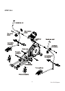
STEP 2: CONSOLE MAST ASSEMBLY
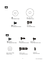
1. Remove the hardware from the hardware pack for step 2. You should have one 2-1/4 X
3/8 bolt, one lock washer, two 3/4 X 3/8 bolts, two curved washers and four 1/2 X
1/4 Phillips head screws.
2. Locate the console mast and console mast cover and slide the cover onto the mast as
far as it will go. Make sure the cover is facing the correct way.
3. At the top opening of the main body of the elliptical is a wire harness. Unravel and
straighten out the wire harness and feed it into the bottom of the console mast tube and
out of the top opening.
4. Install the console mast into the receiving bracket in the top of the main body. NOTE:
there is one bolt already installed in the receiving bracket that will engage with the slot
at the bottom of the console mast. This needs to be tightened at the end along with the
three other console mast bolts.
Assembly Instructions