


XE Series Elliptical
6
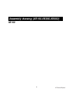
NOTE: there is one bolt already installed in the receiving bracket that will engage
with the slot at the bottom of the console mast. This needs to be tightened at the
end along with the three other console mast bolts.
5. Put the flat washer onto the 2 3/4” bolt and the two curved washers onto the two
1” bolts. Install, and hand tighten, the 2 3/4” bolt through the left side of the
receiving tube into the console mast. NOTE: There is a wire running through the
tube. Be careful not to damage or pinch this wire during this procedure. Damage
to the electronic console could result. Install, and hand tighten, the two 1” bolts
through the front of the receiving tube into the console mast.
6. Using the two sided wrench tighten the three bolts, and the fourth bolt which is
pre-installed, firmly. These bolts should be tightened as much as you possibly
can.
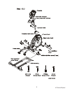
7. Locate the electronic console and the four 1/2” X 1/4” Phillips head screws.
8. There will be two electrical wire connectors at the top opening of the console
mast, one 4 pin (hand pulse sensors), one 10 pin (main wire harness). Connect
these to the mating connectors on the back of the console. The connectors are
keyed so you cannot plug them in the wrong way so do not force them.
9. Storing the excess wire back into the console mast, carefully install the console
onto the mounting plate and secure using the four Phillips head screws.
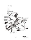
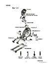
STEP 3: HANDLE BAR ASSEMBLY
1. Remove the hardware from the hardware pack for step 3. You should have two
5/8” X 3/8” bolts, two large flat washers, two large wave washers and four self
tapping Phillips head screws.
2. Locate and install the 2 large wave washers onto the handle bar axle, one on
each side.
3. Slide the left and right handle bars onto the appropriate side of the axle. There is
a sticker on each handle bar indicating L for left and R for right.
4. Put the large flat washers onto the two 5/8” X 3/8” bolts and install, and tighten,
in the threaded holes in the ends of the axle.
5. Install the plastic covers over the handle bar/axle connections with the six self
tapping Phillips head screws.
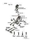
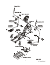
STEP 4: FOOT PAD/CONNECTING ARM ASSEMBLY
1. Remove the hardware from the hardware pack for step 4. You should have two
1-1/4” X 3/8” bolts, two flat washers, two Nyloc® nuts, four 5/8” machine screws
(long), four 3/8” machine screws (short) and two self tapping Phillips head