22
P/N M601111 08/05
21
21
49
25
34
1
32
32
57
20
34
20
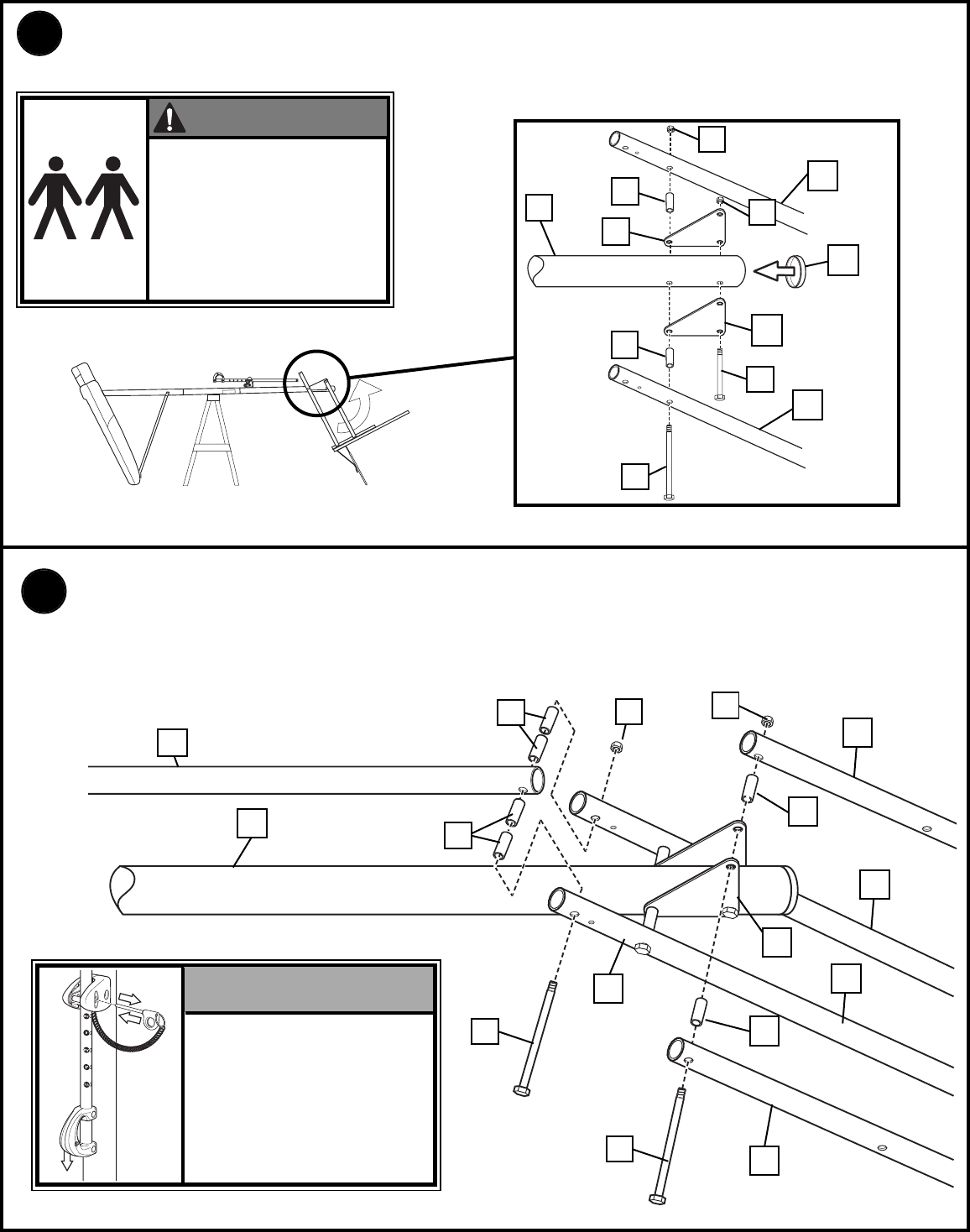
10.
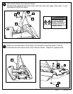
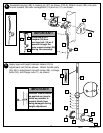
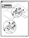
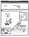
Support pole on sawhorse. Attach backboard assembly to top pole section (4) as
shown. Install pole cap (25).
57
34
33
20
21
1
21
33
20
32
58
11.
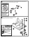
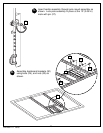
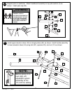
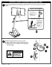
Install upper elevator tubes (33) to triangle plates (63) as shown. Install handle assembly
to lower elevator tubes (34) using bolt (57), spacers (20), and nut (21) as shown.
57
34
34
20
20
U
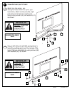
SE CAUTION; ELEVATOR
A
SSEMBLY IS HEAVY.
T
WO PEOPLE REQUIRED FOR
THIS PROCEDURE. FAILURE
TO FOLLOW THIS WARNING
C
OULD RESULT IN SERIOUS
INJURY AND/OR PROPERTY
DAMAGE.
WARNING!
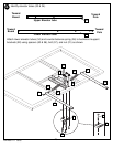
Before going on to
next step, set
adjustable system
assembly to the
10’ (3.05 m) setting.
NOTE:


