


8
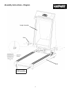
Assembly Instructions
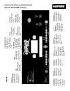
The 9.3 treadmill is shipped in one box with two pieces, the base frame and the upright/console
assembly. The following steps should be followed for assembling the treadmill:
Remove any packing materials from the treadmill. Do not throw away any packing materials until
assembly is completed. You should find the following:
1. Base Frame
2. Double triangular upright assembly with console
3. Two plastic boots to cover gap between upright assembly and base (see Diagram next page).
There is one for the left side, and one for the right side.
4. Two plastic roller end caps.
5. Owner’s Manual Packet contains:
•
Owner’s Manual,
•
Eight pieces: pan head #8 x 3/4” assembly screws for boots and roller end caps
•
Six pieces: #18 x 5/16” x 3/4” Button head bolts for upright/base assembly (3 each side)
•
Two pieces: #8 5/8” Phillips pad head screws for front of upright/base attachment
•
Allen wrench for belt adjustment
•
Plastic Allen wrench holder with tape side (to attach to treadmill frame)
•
Chest Strap Transmitter (for Heart Rate HR models only)
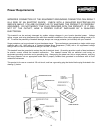
Place the base on a clean, level surface. Make sure the electrical cord will easily reach an electrical
outlet. It is recommended to use two people to assemble the upright assembly on to the base frame.
WARNING: Do not plug treadmill in until assembly is complete. Failure to follow this warning
could result in electrical shock and/or injury.
1. Before beginning, read all instructions before starting and become familiar with the parts. In addi-
tion, look at the motor controller circuit board on the base and find the slot where the wire harness
plugs in before beginning.
2. Have one person lift the upright assembly.
3. Have the other person find the wire harness exiting from the left upright. Plug wire harness into
motor controller circuit board. (See Diagram next page).
4. Slowly lower the upright assembly on to the base while aligning up the bolt holes.
5. Install upright / base bolts loosely using #18 x 5/16” x 3/4” Button head bolts (3 each side).
6. Install the plastic boots to cover gaps between upright assembly and base with #8 x 3/4” pan head
screws (see Diagram next page).
7. Install plastic roller end caps with #8 x 3/4” pan head screws (see diagram for orientation).
8. Securely tighten all bolts and screws.
9. Assembly is now complete.
10. Be sure that the treadmill is level to the floor. The rear feet can be adjusted to level the treadmill.
Assembly is now complete!