


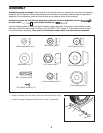
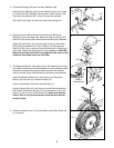
5. Press an Access Cover (14) into the hole in each Side Shield (50,
51) as shown.
5
14
50
51
5
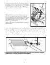
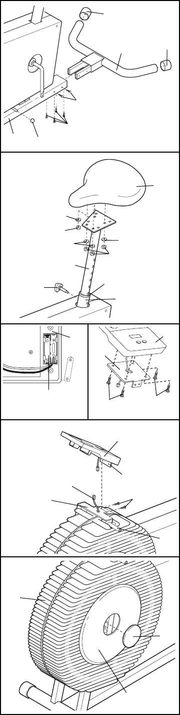
2. Press two Endcaps (40) onto the Rear Stabilizer (39).
Slide the Rear Stabilizer (39) into the indicated end of the Frame
(1). Attach the Rear Stabilizer with two M6 x 16mm Screws (49)
from each side and four M6 x 16mm Screws from beneath.
Tap a 3/8Ó Push Cap (19) onto each end of the locking rod.
3. Remove the four M8 Locknuts (32) and the four M8 Spring
Washers (3) from the Seat (48). Attach the Seat to the top of the
Seat Post (42) with the M8 Locknuts and the M8 Spring Washers.
Adjust the Seat (48) to the desired height. Insert the Seat Knob
(52) through the welded nut on the Frame (1) and through the
Seat Post (42). Next, press the Frame Bushing (43) into the top of
the Frame. Tighten the Seat Knob into the welded nut. CAUTION:
Make sure to insert the Seat Pin through the Seat Post; do not
insert the Seat Knob under the Seat Post.
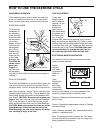
4. The Electronic Monitor (46) requires two "AA" batteries (not includ-
ed). Alkaline batteries are recommended. Find the markings inside
the battery compartment showing which direction the batteries
must be turned. Insert the batteries into the battery compartment.
Attach the Monitor Bracket (27) to the back of the Electronic
Monitor (46) with the four Console Screws (44).
Insert the Handlebar Shaft (54) into the Frame (1).
Plug the Sensor Wire (21) into the wire on the Electronic Monitor
(46). Attach the Monitor Bracket (27) and the Monitor (46) to the
Frame (1) with two 3/16Ó Small Screws (2). Make sure that the
Sensor Wire is not pinched between the Electronic Monitor
and the Frame.
27
46
44
1
40
48
32
32
52
42
1
43
49
40
2
3
4
39
49
19
3
3
3
44
46
46
21
54
2
1
Battery
Compartment
27