


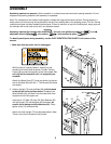
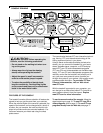
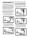
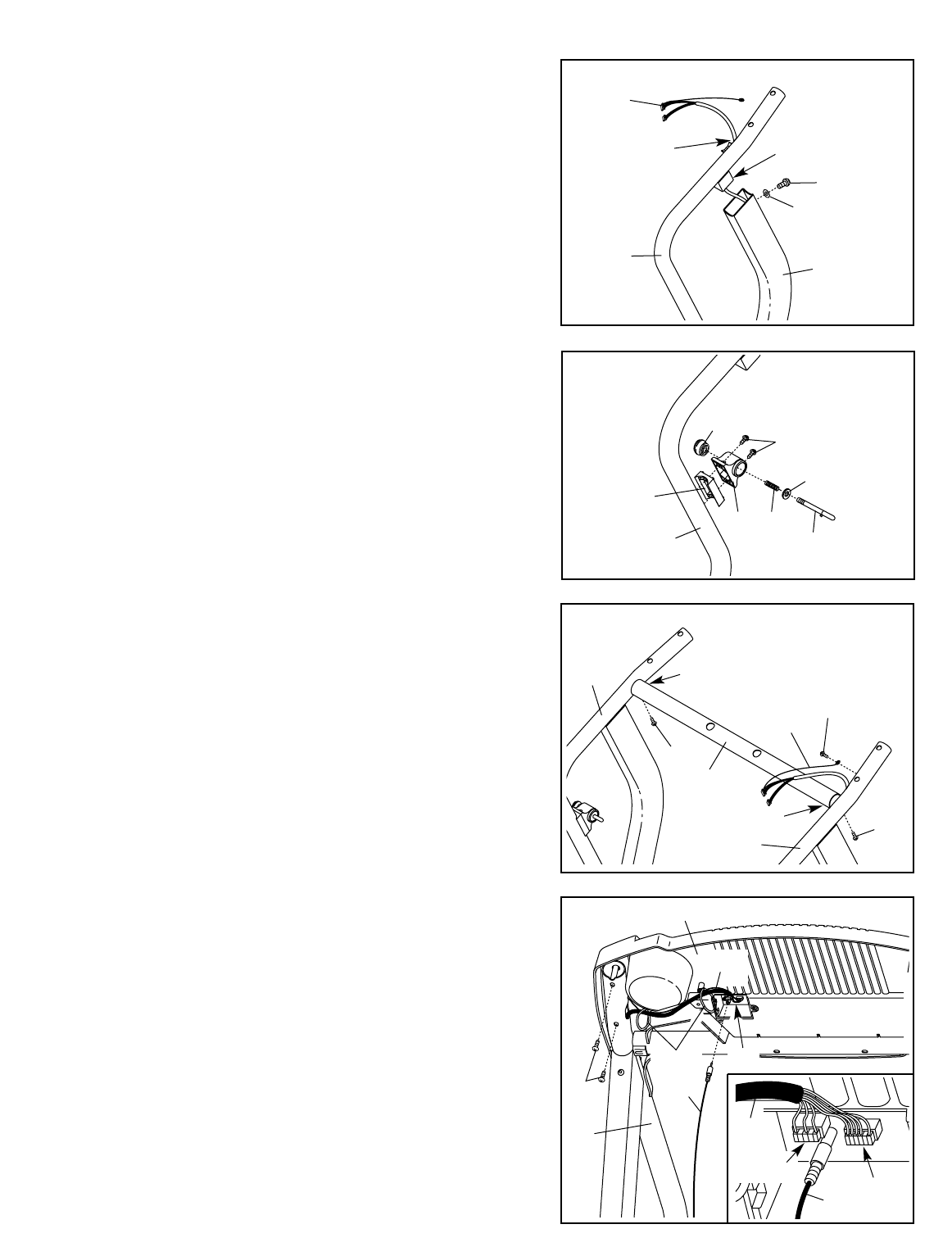
5. Set the Crossbar (40) on the brackets on the Handrails
(71, 72). Attach the Crossbar with two Crossbar Screws
(39).
Do not tighten the Crossbar Screws yet.
Attach the end of the ground wire to the small hole in the
side of the Right Handrail (72) with a Silver Ground
Screw (77).
Ground
Wire
72
71
39
Bracket
Bracket
40
39
77
5
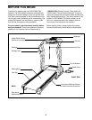
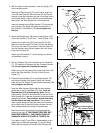
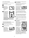
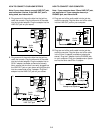
3. With the help of a second person, raise an Upright (73)
to the vertical position.
Identify the Right Handrail (72), which has a large hole
in the left side. Feed the Wire Harness (42) up into the
bracket on the Right Handrail and out of the large hole in
the left side. Note: It may be helpful to use needlenose
pliers to pull the Wire Harness out of the large hole.
Insert the bracket on the Right Handrail (72) into the top
of the Upright (73). Attach the Right Handrail with a 1”
Bolt (63) and a Flat Washer (76).
Do not tighten the
Bolt yet.
Bracket
72
73
42
3
63
76
Large
Hole
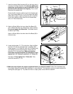
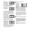
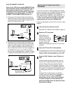
4. Attach the Storage Latch (36) and the Latch Spacer (107)
to the Left Handrail (71) with two 1” Latch Screws (112).
Remove the Latch Knob (30) from the Latch Pin (35).
Make sure that the Latch Pin Collar (33) and the Spring
(32) are on the Latch Pin as shown. Insert the Latch Pin
into the Storage Latch (36) and tighten the Latch Knob
back onto the Latch Pin.
Attach the Left Handrail (71) to the Upright (not shown)
as described in step 3.
35
33
32
36
30
71
107
112
4
47
Ties
72
56
6
42
2
5-wire
56
43
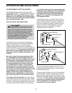
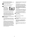
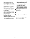
6. Place the Console Base (47) on the Right Handrail (72)
and the Left Handrail (not shown). Attach the Console
Base with six 3/4” Screws (2) (two Screws are shown). Do
not overtighten the Screws.
Insert the Wire Harness (42) through the two indicated
plastic ties on the Console Base (47). Next, touch the
Right Handrail (72) to discharge any static.
See the
inset drawing. Find the 3-wire connector on the end of the
Wire Harness (42). Insert the connector into the red socket
beneath the console.
The connector should slide easily
into the socket and snap into place. If the connector
does not slide easily and snap into place, turn the connec-
tor and then insert it. Insert the 5-wire connector into the
black socket beneath the console in the same way.
Make sure that the connectors and wires appear as
shown at the right.
IF THE CONNECTORS ARE NOT
INSERTED PROPERLY, THE CONSOLE MAY BE
DAMAGED WHEN THE POWER IS TURNED ON.
If you plan to use iFIT.com CDs or videocassettes, or pro-
grams from our Web site (see page 13), plug the Audio
Cable (56) into the jack on the back of the Console (43).
6
42
3-wire