


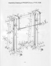

7. Attach
the two
Rear Support
Frames
(4)
to the two base
rails
(1
& 2) using four bolts
(22),
eight washers
(18)
and four nuts
(20)
as shown.
HAND TIGHTEN the
bolts
at
this time.
8. Attach the two
Pulley Support Frames
(17)
to the
Rear Support Frames
(4)
and the Upright Guide Posts
(10
&
12) using eight bolts
(28),
sixteen washers
(18)
and
eight
nuts
(20)
as shown. HAND TIGHTEN
the bolts
at this time.
9.
Attach
the
Upper Cross Brace
(11)
to the
two Rear Support
Frames
(4)
using
four bolts
(51),
eight washers
(18)
and four nuts
(20)
as shown.
HAND TIGHTEN the bolts
at this time.
'10.
Tighten all bolts and nuts used
for assembly
in
previous
steps.
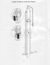
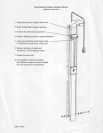
11. Carefully
insert the Left Weight Bar
Knuckle
(44)
up through the rectangular cutout in the Pulley Support
Frame
(17)
and flex the Left
Weight Bar Cables
(24)
onto the
pulleys (27)
so that the cables
insert
into the
grooves
of
each corresponding
pulleys
and allowing
the Left Weight Bar Knuckle
(44)
to hang free. Be
sure
that the cables are
straight and uncrossed and
cables and
pulleys
move smoothly.
12. Repeat the step
11
on the
right
side
of the PROSPOT/nsssrM
PC-1000.
STEP
#2:
SENSOR
WEIGHT BAR
INSTALLATION
1.
Standing
in front of the PROSPOTlrressrM
PC-1000. Insert one end and
then the
other
end
of the
Sensor
Weight Bar
(25)
into the Knuckles
(42
&
44). Slide the knuckles onto the Bar until they rest snugly
against
the
preinstalled
sensor retaining collars
(45
& 48) at each end of the Sensor Weight Bar
(25). (There
is
a
rotation limi{ing
pin
that
protrudes
from the bottom of the Sensor Weight Bar
(25)
that must fit through
a slot
in the knuckles
g?
A 44t as
it
is slid
into
position).
2. Place one Plastic Locking Sleeve
(39)
onto
each end of the Sensor Weight Bar
(25)
and slide them inwards
until they butt up against and secure
the Weight Bar Cable
Knuckle
in
place.
Tighten Plastic Locking Sleeve
bolts securely.
3. Place one of the Olympic Adapters
(30)
onto the Sensor
Weight Bar
(25)
and slide them onto the Bar until
they touch the Plastic Locking Sleeves
(39).
Insert an Olympic Adapter Retaining Plug
(33)
onto each end
of the Sensor Weight Bar
(25)
so that they also
go
inside of the Olympic Adapters
(30).
Secure with two
Allen
bolts
(29),
two washers
(36)
and two spring
washers
(56).
4. Attach the four small
plastic pipes (15)
to the two
Pulley
Support
Frames
(17)
using
four
bolts
(34),
eight
washers
(38)
and four nuts
(35)
as shown.
Tighten the
bolts securely.
5.
Attach
the six Side Weight Plate
Holders
(14)
to the two Rear Support Frames
(4)
using
twelve bolts
(53),
twenty-four washers
(18)
and twelve nuts
(20)
as shown. Tighten the bolts securely.
6.
Carefully thread the
rear
ends
of the Cross Brace Wire
Harness
(8)
through the middle hole
on the
Electronic Box Locating
Plate
(13)
and
then attach the Locating Plate
(13)
to the Lower
Cross Brace
(3)
using two bolts
(22),
four
washers
(18)
and two
nuts
(20).
Tighten the bolts securely.
7. Attach
the
Electronic Box Protecting Cover
(5)
to the
Locating Plate
(13)
using two cross screws
(52)
and
lwo washers
(57)
as shown. Tighten the screws
securely.
Note: In this manual when referring to Left and
Right
side of unit, the left and right
perspective
are from
the
outside, facing
the
front of the unit.
--2--