


5
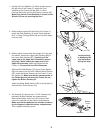
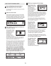
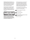
1. Identify the Front Stabilizer (3). While another person
l
ifts the front of the Frame (1), attach the Front
Stabilizer to the Frame with two M10 x 112mm
C
arriage Bolts (34) and two M10 Nylon Locknuts (29).
Make sure that the Front Stabilizer is turned so the
Wheels (32) are not touching the floor.
3
29
32
32
34
1
1
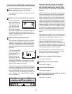
2. While another person lifts the back of the Frame (1),
attach the Rear Stabilizer (4) to the Frame with two
M10 x 112mm Carriage Bolts (34) and two M10 Nylon
Locknuts (29).
34
4
1
3
2
86
87
1
63
83
70
70
91
105
83
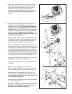
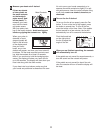
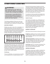
3. While another person holds the Upright (2) in the posi-
tion shown, connect the Upper Wire Harness (86) to
the Lower Wire Harness (87). Carefully pull the
upper end of the Upper Wire Harness to remove
any slack. While holding the upper end of the
Upper Wire Harness,
insert the Upright into the
Frame (1). Do not pinch the Wire Harnesses.
Slide an M10 Split Washer (70) and a Frame Spacer
(83) onto each of the two M10 x 88mm Button Screws
(63). Insert the Button Screws into the Frame (1) and
the Upright (2). Make sure that the concave ends of
the Frame Spacers are facing the Frame. Do not
tighten the Button Screws yet.
Attach the Water Bottle Holder (105) to the Upright (2)
with two M4 x 22mm Screws (91).
2
29
29
Avoid pinching
or damaging the
wire harnesses
during this step.
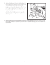
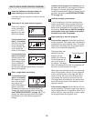
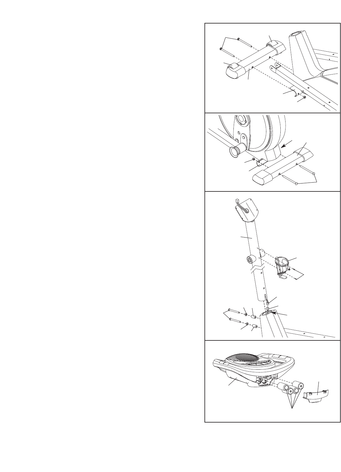
4. The Console (5) requires four 1.5V “D” batteries (not
included); alkaline batteries are recommended.
Remove the battery cover from the Console. Next,
insert four batteries into the battery compartments.
Make sure that the batteries are oriented as shown
by the diagrams inside the battery compartments.
Then, replace the battery cover.
4
5
Batteries
Battery
Cover