9
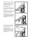
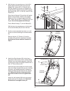
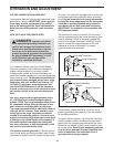
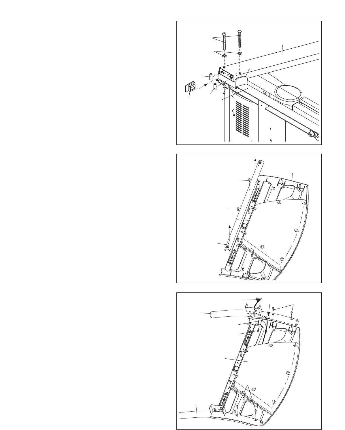
8. Identify the Right Handrail (90), which has a
large hole in the location shown. Hold the Right
Handrail near the console assembly. Attach the
console ground wire to the Right Handrail with a
#8 x 1/2" Ground Screw (87).
Insert the end of the console wire into the large
hole in the Right Handrail (90) and out of the top
as shown; use needlenose pliers if necessary.
Attach the Right Handrail with two 3/4" Screws
(12). Make sure that no wires are pinched.
Start both Screws but do not tighten them
yet.
Attach the Left Handrail (88) to the console as-
sembly with two 3/4" Screws (12). Start both
Screws but do not tighten them yet.
12
12
90
88
87
Console Wire
Ground Wire
Hole
8
Console
Assembly
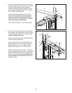
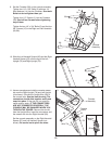
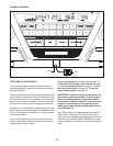
7. Set the console assembly face down on a soft
surface to avoid scratching the console assem-
bly.
Remove the two 1/2" Screws (1) from the
Crossbar (39), and then remove the Crossbar.
Save the two Screws and the Crossbar for
step 9.
Console
Assembly
1
1
39
7
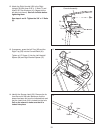
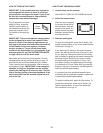
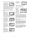
6. With the help of a second person, hold a Bolt
Spacer (80) inside the lower end of the Left
U
pright (74). Insert a 3/8" x 4" Bolt (6) with a
3/8" Star Washer (9) into the Left Upright and
t
he Bolt Spacer. Repeat this step with a second
Bolt Spacer (80), 3/8" x 4" Bolt (6), and 3/8" Star
Washer (9).
O
rient the Left Upright (74) and the Left Upright
Spacer (76) as shown. Hold the Left Upright
Spacer and the Left Upright against the Base
(83). Tighten the two 3/8" x 4" Bolts (6) with your
fingers;
do not fully tighten the Bolts yet.
Press a Base Endcap (77) into the Base (83).
With the help of a second person, tip the tread-
mill so that the Base (83) is flat on the floor.
7
6
74
6
83
80
80
77
9
6


