


8
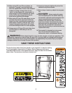
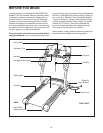
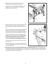
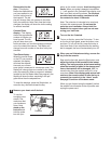
7. With the help of another person, hold the console as-
sembly near the Right Upright (82) and the left Upright
(not shown).
Connect the Wire Harness (83) to the wire harness in
the console assembly.
Make sure to connect the con-
nectors properly (see the inset drawing); the con-
nectors should slide together easily and snap into
place.
If the connectors do not slide together easily and
snap into place, turn one connector and try to connect
them again. IF THE CONNECTORS ARE NOT CON-
NECTED PROPERLY, THE CONSOLE MAY BE DAM-
AGED WHEN THE POWER IS TURNED ON.
Insert the
excess wire harness back into the right handrail.
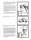
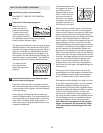
Set the console assembly on the Right Upright (82) and
the Left Upright (not shown). Thread two 1/4” x 1” Bolts
(71) with 1/4” Star Washers (92) into each side of the
console assembly.
After you have started all four
Bolts, tighten them.
82
Console
Assembly
83
92
71
83
7
Right Handrail
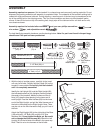
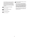
6. Attach the Console Back (95) to the console assembly
with five 3/4” Screws (6).
95
6
Console Assembly
6
6
6
68
114
110
88
7
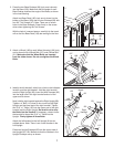
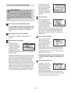
5. Turn the Console (88) upside-down; be careful not to
scratch the Console. Remove the bands and the Console
Back (95) (see drawing 6) from the Console. If the four
Pulse Bar Screws (68) (only two are shown) are in the
Console Frame (7), remove them.
Hold the ends of the Pulse Bar (110) against the Console
Frame (7) as shown. Connect the pulse wire in the
Console (88) to the pulse wire in the Pulse Bar (see the
inset drawing).
The connectors should slide together
easily and snap into place. If the connectors do not
slide together easily and snap into place, turn one con-
nector and try again to connect them. Attach the Pulse
Bar to the Console Frame with the four Pulse Bar Screws
(68).
Firmly tighten the Pulse Bar Screws. Be careful
not to damage the wires.
Attach the ring on the ground wire to the Console Frame
(7) with a 1/2” Ground Screw (114). Note: There are no
wires on the other side of the Pulse Bar (110).
Ground
Wire
Pulse
Wire
Pulse
Wire
5