


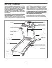
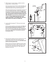

5
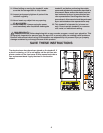
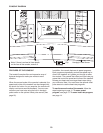
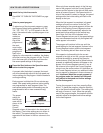
. Place the treadmill in the storage position (see HOW TO
FOLD AND MOVE THE TREADMILL on page 17).
Next, place the cylinder end of the Gas Spring (19) near
t
he bracket on the base of the Uprights (84).
See the two small inset drawings. Using your fingernail
or the end of a screwdriver, press on the end of the Gas
Spring Pin (18) to loosen it from the Gas Spring (19).
Next, rotate the Gas Spring Pin and pull it out of the Gas
Spring. Be careful to avoid losing the Gas Spring Pin.
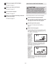
See drawing 5a. Press the cylinder end of the Gas
Spring (19) onto the ball on the bracket. Next, insert the
end of the Gas Spring Pin (18) through two of the small
holes in the end of the Gas Spring. Then, rotate the Gas
Spring Pin until it clips onto the Gas Spring.
19
18
19
18
5
5a
84
Bracket
C
ylinder
Piston
Bracket
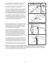
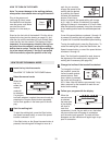
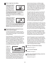
6.
Raise the Gas Spring (19) to a vertical position. Remove
the Gas Spring Pin (18) from the raised end of the Gas
Spring as described in step 5. If necessary, rotate the
Gas Spring to align the end of the Gas Spring with the
ball on the bracket on the Frame (58).
Plug in the power cord as described on page 9. Turn on
the power as described on page 11. Next, press the
Incline increase and decrease buttons until the ball on
the bracket is aligned with end of the Gas Spring (19).
Then, press the end of the Gas Spring onto the ball.
Note: It may be necessary to press the end of the Gas
Spring onto the ball while the Frame is moving.
See drawing 6a. Insert the Gas Spring Pin (18) into the
two indicated small holes in the end of the Gas Spring
(19). Then, rotate the Gas Spring Pin until it clips onto the
Gas Spring. Note: Extra Gas Spring Pins are included.
Press the Incline decrease button until the treadmill is at
the lowest incline level. Then, unplug the power cord.
18
19
Holes
18
19
6
6a
58
Bracket
18
18
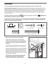
7. Make sure that all parts are properly tightened before you use the treadmill. If there are sheets of clear
plastic on the treadmill decals, remove the plastic. To protect the floor or carpet, place a mat under the tread-
mill. N
ote: Extra hardware may be included. Keep the included allen wrench in a secure place; the large allen
wrench is used to adjust the walking belt (see page 20).
8