


ASSEMBLY
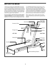
Assembly requires two persons. Set the treadmill in a cleared area and remove all packing materials; do not
dispose of the packing materials until assembly is completed. Note: The underside of the treadmill walking
belt is coated with high-performance lubricant. During shipping, a small amount of lubricant may be transferred to
the top of the walking belt or the shipping carton. This does not affect treadmill performance. If there is lubricant
on top of the walking belt, simply wipe off the lubricant with a soft cloth and a mild, non-abrasive cleaner.
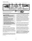
Assembly requires the included allen wrench and your own phillips screwdriver , flat head
screwdriver and adjustable wrench .
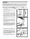
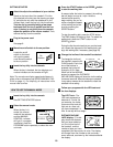
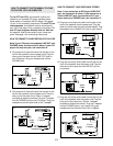
2. Identify the Right Upright (103), which has a Pulse Wire
(121) inside of it.
Have a second person hold the Console Base (64) near
the Right Upright (103) as shown. Feed the Wire
Harness (90) into the indicated hole near the upper end
of the right Upright and out of the hole near the lower
end of the Right Upright.
Connect the Wire Harness (90) to the Base Wire Harness
(126). If the connectors do not fit together easily, ro-
tate them and then connect them. Insert the connectors
into the Right Upright (103). Be careful not to damage
the Wire Harness during steps 2 through 6.
103
126
118
90
90
Hole
121
64
2
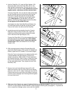
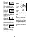
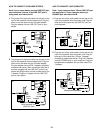
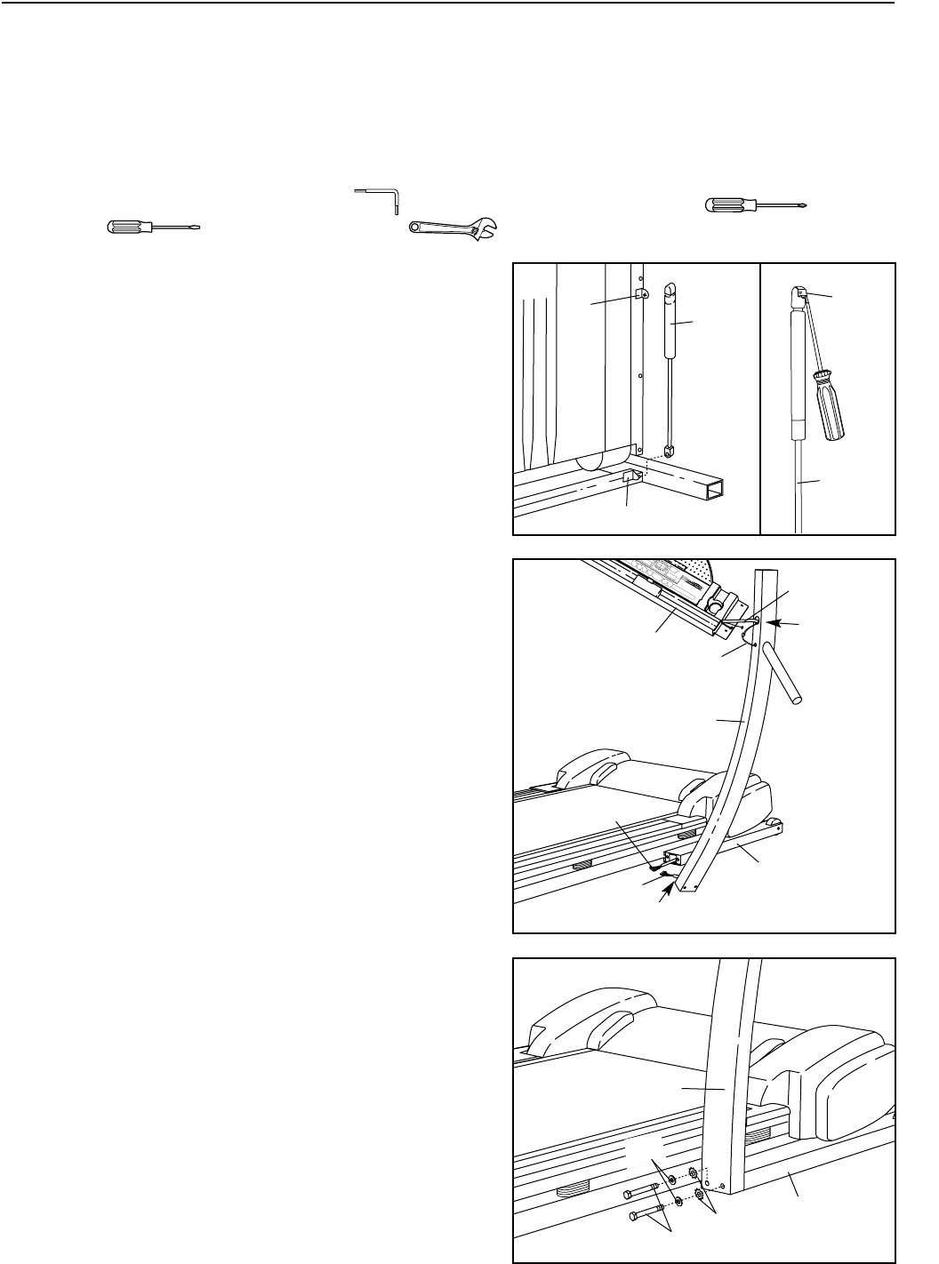
3. Have a second person hold the Right Upright (103) and
the Console Base (not shown) in a vertical position.
Hold the Right Upright (103) against the Base (118) as
shown. Hand tighten two Upright Bolts (84) with
Washers (125) and Star Washers (89) into the Right
Upright and the Base; do not tighten the Upright Bolts
yet. Be careful not to pinch the Wire Harness (not
shown) inside of the Right Upright.
Attach the Left Upright (not shown) as described above.
Note: There are no wires in the Left Upright.
103
89
118
84
3
6
125
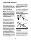
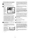
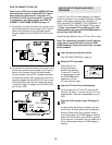
1. Raise the Frame (79) to a vertical position. Be careful
not to overextend the Frame.
Press the bottom end of the Shock (60) onto the bracket
on the Base (118) as shown.
Press the top end of the Shock (60) onto the bracket on
the Frame (79). If necessary, move the Frame (79) for-
ward or backward to align the end of the Shock with the
bracket. It may be helpful to use a flat head screwdriver
(see the small drawing) to lift the metal clip on the end of
the Shock as you press the Shock onto the bracket. Do
not remove the clip. Carefully lower the Frame (79).
60
79
118
Hole
1
60
Clip