


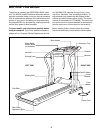
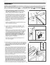
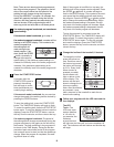
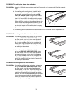
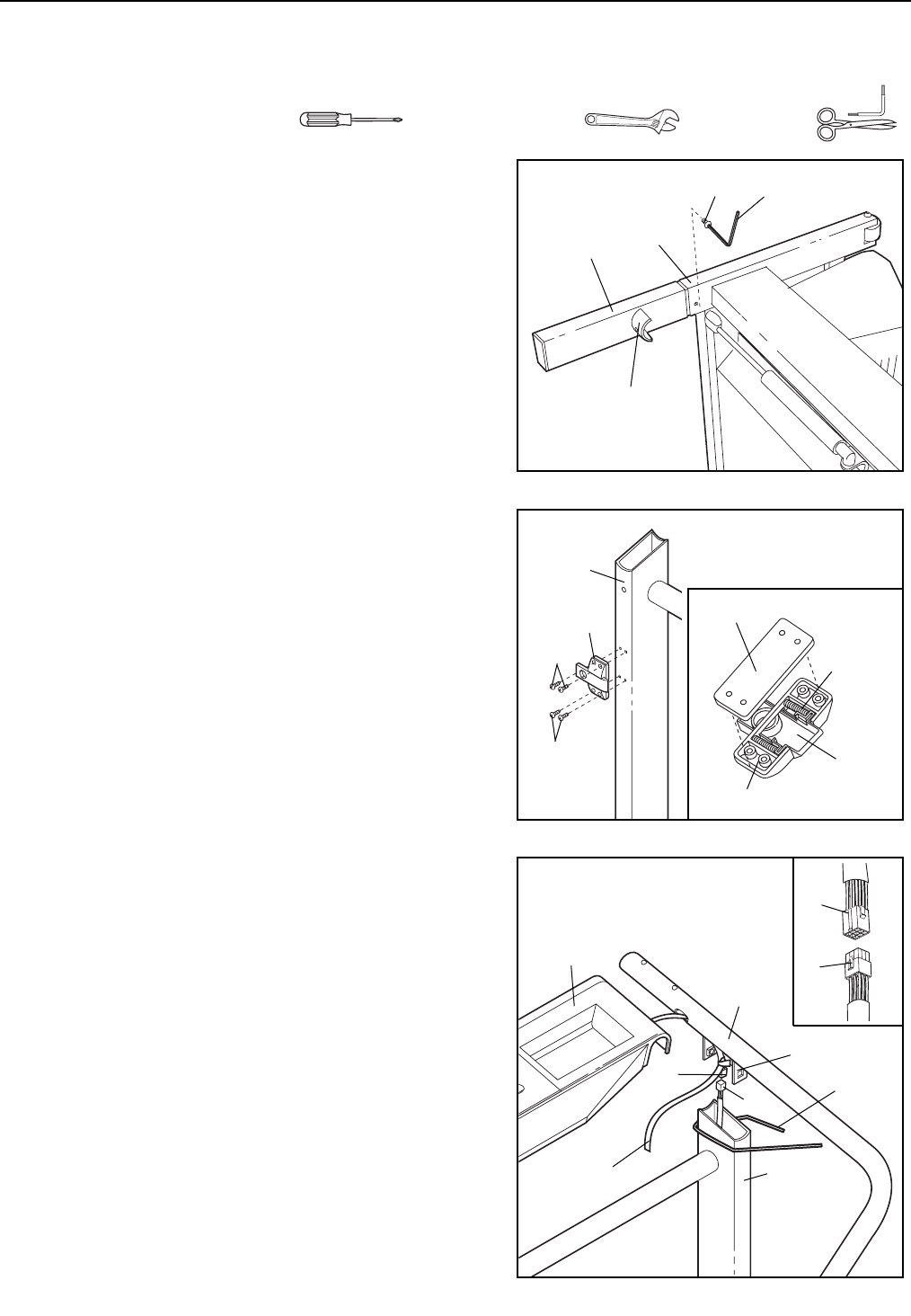
1. Refer to the drawing on page 4 and identify the
right side of the treadmill. With the help of a second
person, carefully lay the treadmill on its right side.
Firmly slide an Extension Leg (59) into one side of the
Base (32). Make sure that the Extension Leg is turned
so the bracket is on the side shown. Using the Allen
Wrench (102), tighten an Extension Leg Screw (57) into
the Extension Leg and the Base. Without turning the
treadmill over, attach the other Extension Leg in the
same manner.
Stand the treadmill upright so that both Extension Legs
(59) are resting flat on the floor.
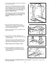
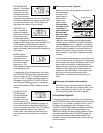
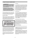
3. Cut the plastic ties holding the cage nut and Wire Harness
(35) in the upper end of the Right Handrail (62). Note: Be
careful not to drop the Wire Harness down the right
Upright (32).
While a second person holds the Console Base (46) and
the Right Handrail (62) near the right Upright (32), locate
the wire tie attached to the Console Wire Harness (90).
Route the wire tie and the Console Wire Harness into the
Right Handrail and out of the indicated bracket. Pull as
much of the Console Wire Harness through the Right
Handrail as possible. It may be helpful to turn the Console
over as you route the wire.
Next, connect the Wire Harness (35) to the Console Wire
Harness (90). Refer to the inset drawing. The latch on the
Wire Harness should snap onto the Console Wire Harness.
If the Wire Harnesses do not fit together easily, turn
them; do not force the Wire Harnesses together.
Remove the wire tie from the Console Wire Harness (90).
Insert the slack Wire Harness into the Right Upright (32).
57
102
59
32
Bracket
1
62
90
46
35
32
Bracket
Plastic
Tie
Wire Tie
3
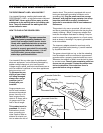
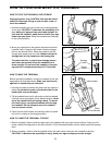
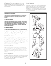
2. Refer to HOW TO LOWER THE TREADMILL FOR
USE on page 11. Follow the instructions in step 2 to
lower the treadmill.
Without removing the tape from the Latch (34), hold the
Latch against the left Upright (32) as shown. Attach the
Latch to the left Upright with four Screws (33). Make
sure that the Screws are tight, but do not over-
tighten them; if the Screws are overtightened, the
Latch will not slide smoothly. After the Latch is at-
tached, remove any visible tape.
Note: The inset drawing shows how the parts of the
Latch (34) fit together.
34
33
33
32
2
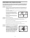
ASSEMBLY
Assembly requires two people. Set the treadmill in a cleared area and remove all packing materials. Do not dis-
pose of the packing materials until assembly is completed. Assembly requires the included allen wrench
and your own phillips screwdriver , adjustable wrench , and scissors .
Spacer
Springs
Bracket
Latch
90
35
5