


ASSEMBLY
Assembly requires two persons. Set the treadmill in a cleared area, and remove all packing materials except
for the plastic ties around the upper body arms. Do not dispose of the packing materials until assembly is
completed. Note: The underside of the treadmill walking belt is coated with high-performance lubricant. During
shipping, a small amount of lubricant may be transferred to the top of the walking belt or the shipping carton. This
does not affect treadmill performance. If there is lubricant on top of the walking belt, simply wipe off the lubricant
with a soft cloth and a mild, non-abrasive cleaner.
Assembly requires the included allen wrench and your own phillips screwdriver ,
adjustable wrench , wire cutters , and a rubber mallet .
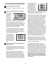
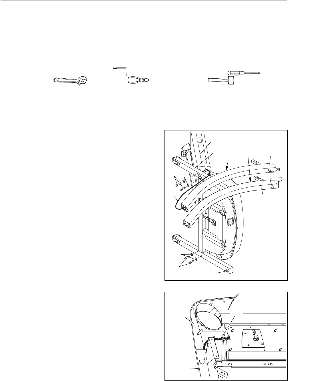
1
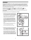
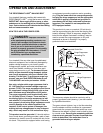
1. With the help of a second person, carefully tip the tread-
mill onto its left side as shown. Partially fold the Frame
(51) so that the treadmill will be more stable. Do not fully
fold the treadmill until it is completely assembled.
Identify the Right and Left Uprights (55, 64); the Left
Upright has two small holes near the square post.
Hold the Right Upright (55) near the Base (116) and ori-
ent it as shown; make sure that the Right Upright
bends in the direction shown. Straighten the Wire
Harness (49), and feed it into the lower end of the Right
Upright and out of the upper end. Hand tighten two
Upright Bolts (112) with Star Washers (111) into the bot-
tom of the Base (116) and the lower end of the Right
Upright.
Attach the Left Upright (64) as described above. Note:
There is not a wire harness on the left side.
Note: One extra Base Pad (44) may be included.
Note: Use the PART IDENTIFICATION CHART in the center of this manual to identify small parts used
during assembly.
Do not plug in the power cord until all assembly steps are completed.
111
64
51
Bend
55
Holes
116
112
112
44
111
49
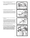
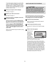
2
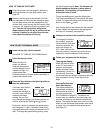
2. With the help of a second person, carefully tip the tread-
mill back down so that the Uprights (55, 64 [not shown])
are vertical. Make sure that the end of the Wire
Harness (49) does not fall into the Right Upright.
Set the Console Base (38) on the Right Upright (55) as
shown. Check the pins in the connector on the Wire
Harness (49) to make sure they are straight. Next, con-
nect the Wire Harness to the indicated connector on the
back of the Console Base. If the connectors do not fit
together easily, rotate them and then connect them.
38
49
55
6