


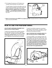
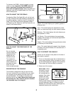
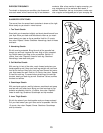
HOW TO ADJUST THE REED SWITCH
If the console does not display correct feedback, the
reed switch should be adjusted. To adjust the reed
switch, the Left Side Shield (11, not shown) must first
be removed as described on page 10.
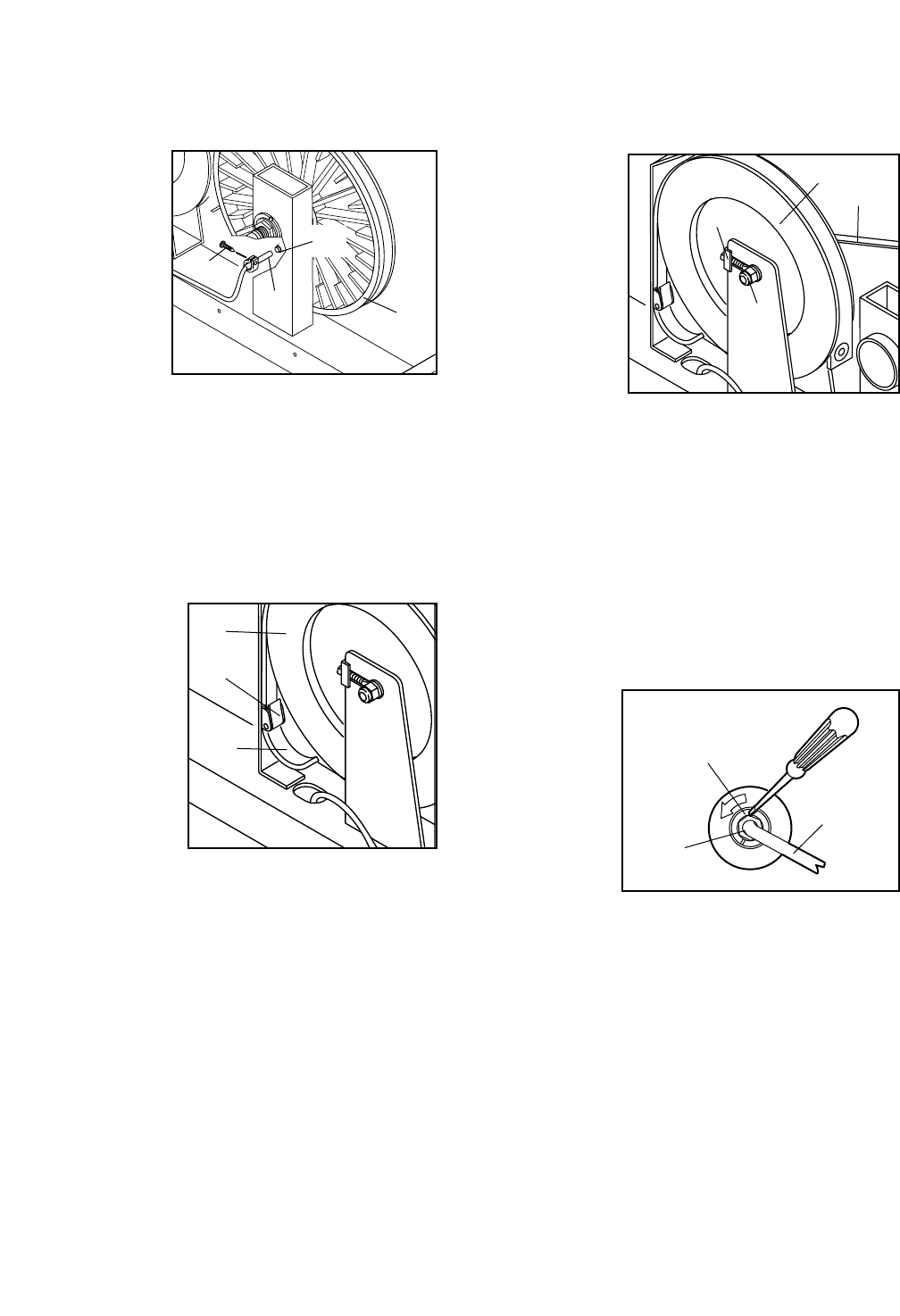
Next, locate the
Reed Switch (48).
Turn the Pulley
(19) until the
Magnet (55) is
aligned with the
Reed Switch.
Loosen, but do
not remove, the
M4 x 12mm
Tapping Screw
(30, shown
removed for clarity). Slide the Reed Switch slightly
toward or away from the Magnet. Make sure that the
Magnet will not hit the Reed Switch. Retighten the
Screw. Turn the Pulley (19) for a moment. Repeat until
the console displays correct feedback. When the Reed
Switch is correctly adjusted, re-attach the left side shield.
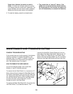
HOW TO ADJUST THE RESISTANCE STRAP
If the pedals do
not have enough
resistance, even
when the resis-
tance knob is
turned to the maxi-
mum setting, the
Resistance Strap
(31) may need to
be adjusted. To
adjust the
Resistance Strap,
the Left Side
Shield (11, not shown) must first be removed, as
described on page 10.
Turn the resistance knob to the lowest setting (see
HOW TO ADJUST THE RESISTANCE OF THE
PEDALS on page 9). Open the Buckle (74) and pull
the end of the Resistance Strap (31) downward slight-
ly. Close the Buckle and turn the Flywheel (20) to
make sure that there is not too much resistance.
When the Resistance Strap is properly adjusted, re-
attach the left side shield.
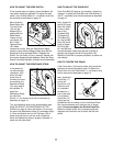
HOW TO ADJUST THE DRIVE BELT
If the Drive Belt (32) slips as you exercise, it should be
adjusted. To adjust the Drive Belt, both Side Shields (11
and 27, not shown) must first be removed as described
on page 10.
Next, loosen the
two M10 Flange
Nuts (23) (there
is one on each
side of the
Flywheel [20]).
To tighten the
Drive Belt (32),
turn the two M6
Nuts (26) clock-
wise; to loosen
the Drive Belt,
turn the M6 Nuts
counterclockwise. Make sure that the Flywheel is
straight and retighten the M10 Flange Nuts (23).
When the Drive Belt is properly adjusted, re-attach the
side shields.
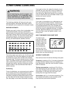
HOW TO TIGHTEN THE CRANK
If the Crank Arms (10) become loose, they should be
tightened to prevent excessive wear. To tighten the
Crank Arms, the Left Side Shield (11, not shown) must
first be removed as described on page 10.
Next, loosen the
Crank Nut (17)
on the left
Crank Arm (10).
Place the end
of a standard
screwdriver in
one of the slots
in the Slotted
Crank Nut (15).
Lightly tap the
screwdriver with a hammer to turn the Slotted Crank
Nut counterclockwise until the arms are no longer
loose. Do not overtighten the Slotted Crank Nut.
When the Slotted Crank Nut is properly tightened,
retighten the Crank Nut and re-attach the left side
shield.
11
20
23
26
32
17
15
10
48
55
30
19
20
31
74