


8
9
21
21
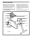
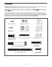
6
10
11
18
Hole
9
71
Console
Wires
Console
Ground
Wire
82
71
16
74
17
6
6
17
9
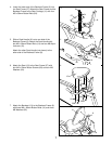
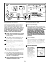
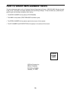
9. While another person holds the Handlebar (16) near
the Upright (6), route the two Pulse Wires (71) into
the Upright and out of the hole at the top of the
Upright.
Next, attach the Handlebar (16) to the Upright (6)
with two M10 x 25mm Button Screws (74) and two
M10 Split Washers (17). Make sure that the Pulse
Wires (71) are not pinched between the Handle-
bar and the Upright.
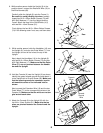
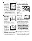
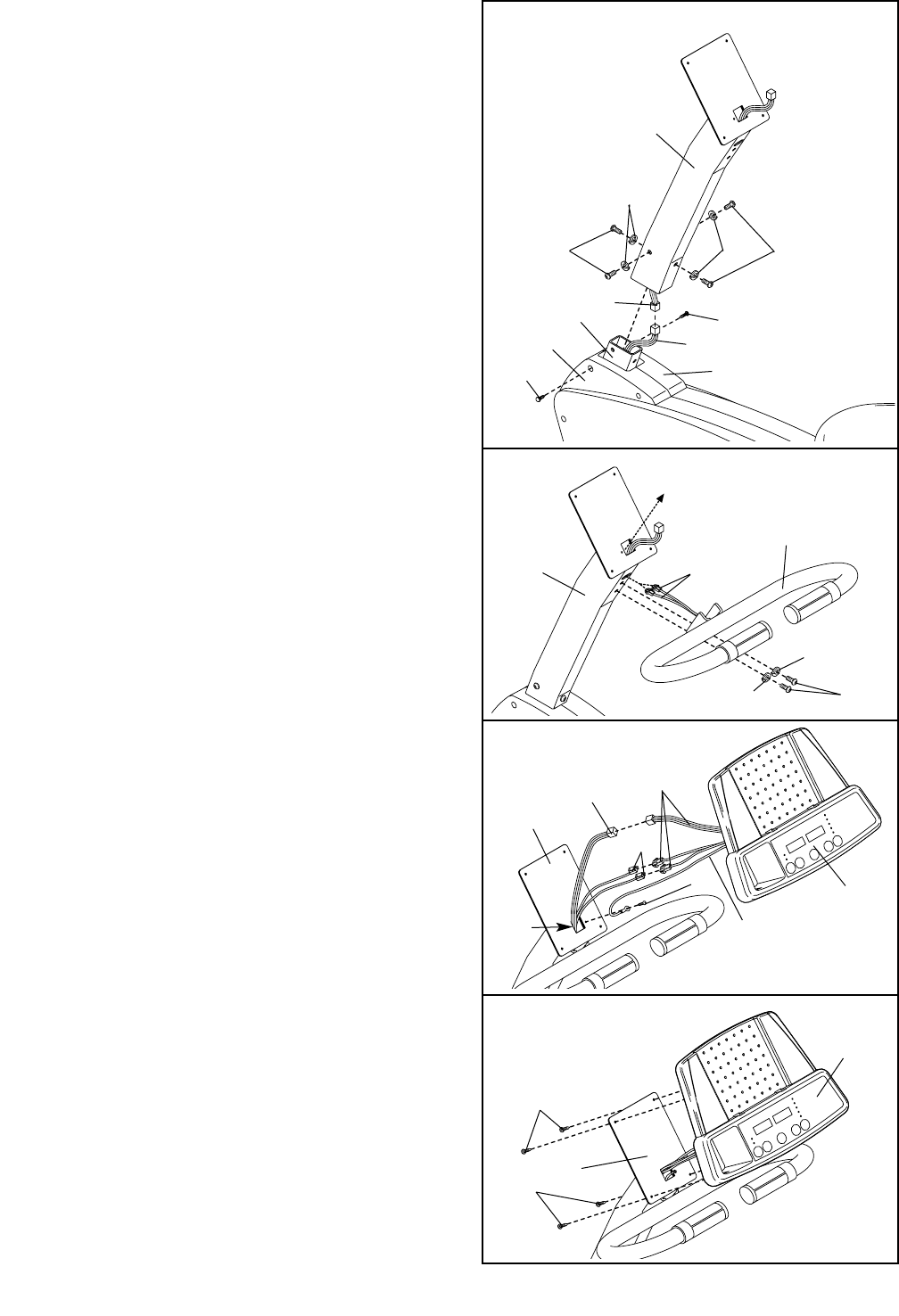
11. Attach the Console (9) to the Upright (6) with the
four M4 x 16mm Screws (21). Make sure that no
wires are pinched between the Console and the
Upright.
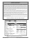
10. Hold the Console (9) near the Upright (6) as shown.
Identify the green console ground wire and attach it
to the Upright with a Ground Screw (82). Make sure
that the console ground wire connector is point-
ed toward the center of the indicated hole as
shown.
Next, connect the Extension Wire (18) and the two
Pulse Wires (71) to the corresponding wires on the
Console (9). Make sure that the wires are not tan-
gled around each other.
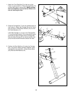
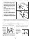
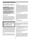
8. While another person holds the Upright (6) in the
position shown, connect the Extension Wire (18) to
the Wire Harness (69).
Carefully slide the Upright (6) onto the Frame (1).
Be careful to avoid pinching the wires. Loosely
thread four M10 x 25mm Button Screws (74) with
M10 Split Washers (17) into the Upright and the
Frame. Attach the tops of the Side Shields (4, 5)
with two M4 x 16mm Screws (21).
Firmly tighten the four M10 x 25mm Button Screws
(74) in the following order: front, rear, and then sides.
6
69
4
5
17
17
18
74
74
Front
Rear
1
21
21
8