38
7
41
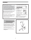
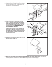
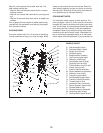
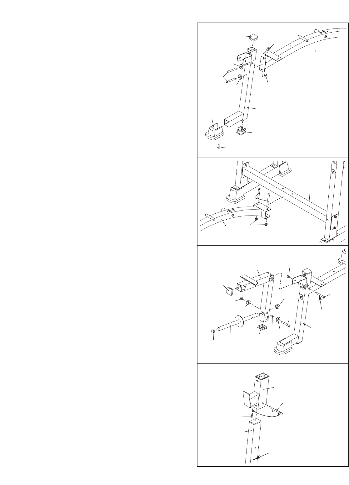
4. Attach a Small Base Foot (14) to the Bench Leg
(2) with an M4 x 16mm Screw (39). Press a
50mm Square Inner Cap (25) and a 50mm
Notched Square Inner Cap (50) into the Bench
Leg.
Attach the Bench Leg (2) to the Bench Frame (1)
with two M10 x 68mm Button Bolt (38), two M10
Washers (41), and two M10 Nylon Locknuts (43).
Do not tighten the Locknuts yet.
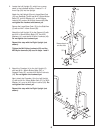
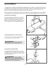
5. Attach the Bench Frame (1) to the Crossbar (4)
with two M10 x 68mm Button Bolts (38) and two
M10 Nylon Locknuts (56). Do not tighten the
Locknuts yet.
Tighten the M10 Nylon Locknuts (43) used in
steps 3–6.
4
5
6
1
2
50
25
41
43
39
14
43
43
38
4
1
25
26
31
49
42
32
43
Lubricate
2
25
26
44
13
7
45
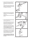
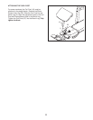
6. Press two 50mm Square Inner Caps (25) into the
Leg Lever (7). Press a 25mm Round Inner Cap
(45) into the Weight Tube (13).
Attach the Weight Tube (13) to the Leg Lever (7)
with an M8 x 63mm Button Bolt (49), two M8
Washers (26), a 12.5mm Spacer (31), and an M8
Nylon Locknut (44). Press the 25mm Round
Angled Cap (32) onto the Weight Tube.
Lubricate an M10 x 73mm Button Bolt (42) with
grease. Attach the Leg Lever (7) to the Bench
Leg (2) with the Bolt and an M10 Nylon Locknut
(43). Do not overtighten the Locknut; the Leg
Lever must be able to pivot easily.
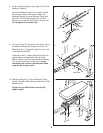
7. Attach the tether on the Weight Rest Pin (23) to a
Weight Rest (11) with an M4 x 16mm Screw (39).
Slide a Weight Rest (11) onto the Left Upright (5).
Insert the Weight Rest Pin (23) into the Weight
Rest and an adjustment hole in the Upright from
the side shown. Rotate the Pin down so that it
wraps around the back of the Upright.
Repeat this step with the other Weight Rest
(11) and the Right Upright (not shown). Make
sure that the two Weight Rests are set at the
same height.
23
39
11
5
Adjustment
Hole
7


