


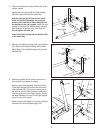
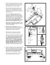
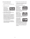
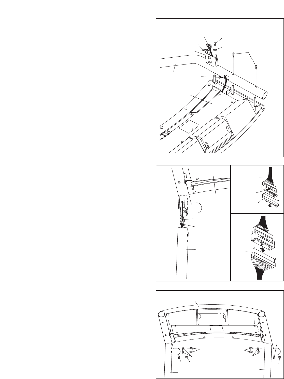
8. See the upper inset drawing. If there is a
guard on the end of the Console Wire, press the
indicated tab and remove the guard with
needlenose pliers. Discard the guard.
With the help of a second person, hold the
Console (91) near the Right Upright (54).
Remove the colored tie from the Wire Harness
(39). Connect the Wire Harness to the console
wire.
See the lower inset drawing. The con-
nectors should slide together easily and
snap into place. If they do not, turn one con-
nector and try again. IF THE CONNECTORS
ARE NOT CONNECTED PROPERLY, THE
CONSOLE MAY BE DAMAGED WHEN THE
POWER IS TURNED ON. Insert the connectors
and excess wire into the Right Upright (54).
8
91
54
39
Console Wire
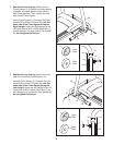
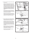
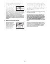
9. Attach the Console (91) to the Right Upright (54)
and the Left Upright (53) with six M8 x 15mm
Bolts (8) and six M8 Star Washers (5).
Make
sure that no wires are pinched. Start all six
Handrail Bolts before tightening them.
With the help of a second person, carefully
lower the Uprights (53, 54) to the floor.
9
8
8
8
5
5
5
8
5
91
54
53
39
9
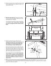
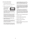
7
. Set the Console (91) face-down on a soft sur-
face to avoid scratching the Console. Hold the
Right Handrail (33), which has a large hole in
the location shown, near the Console.
Next, insert the console wire and tie into the
hole in the side of the Right Handrail (33). If
necessary, use needlenose pliers to pull the
console wire out of the hole near the bracket on
the Right Handrail.
Then, set the Right Handrail (33) on the
Console (91).
Make sure that no wires are
pinched. Start an M5 x 16mm Screw (85) with
an M5 Star Washer (7) into the Right Handrail,
and then start two M4.2 x 19mm Screws (10)
into the Right Handrail.
Tighten the M5 x
16mm Screw and then the two M4.2 x 19mm
Screws; do not overtighten the Screws.
Attach the Left Handrail (not shown) to the
Console (91) in the same way.
Note: There are
no wires on the left side.
7
C
onsole
Wire
Large
Hole
33
B
racket
T
ie
85
7
10
91
Guard
Tab
Console
Wire