


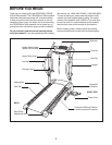

8
87
10
53
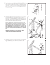
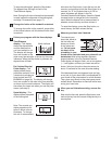
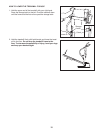
6. Hold the Console (10) near the Console Base (87).
Touch the Right Handrail (16) to discharge any static.
See the inset drawing. Find the 2-wire connector on the
end of the Wire Harness (53). Insert the connector into
the red connector beneath the Console.
The connectors
should slide together easily and snap into place. If
they do not, turn the connector and then insert it. Insert
the 6-wire connector into the socket beneath the Console
the same way.
Insert the excess Wire Harness (53) down through the
opening in the Console Base (87 [see the inset drawing
in step 5]). Securely tighten the plastic tie on top of
the Console Base to prevent the Wire Harness from
slipping. Then, cut off the end of the plastic tie.
Make sure that the connectors and wires appear as
shown at the right. IF THE CONNECTORS ARE NOT
INSERTED PROPERLY, THE CONSOLE MAY BE
DAMAGED WHEN THE POWER IS TURNED ON.
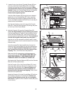
See drawing 6a. Press the Bookrack (85) onto the Console
Base (87) in the location shown.
Set the Console (10) on the Console Base (87). Insert
the excess Wire Harness (53) into the large hole in the
side of the Right Handrail (16). Securely tighten the
plastic ties on the bottom of the Console Base to
prevent the Wire Harness from slipping.
Then, cut off
the ends of the plastic ties.
Attach the Console (10) to the Console Base (87) with two
3/4” Screws (5) and four 1/2” Screws (97)
.
Start all six
Screws before tightening them; do not overtighten
the Screws. Tighten the two Crossbar Screws (98) (only
one is shown).
6
5
5
97
97
98
97
16
Ties
87
6a
6-wire
2-wire
53
8
7
10
Ties
16
5
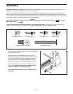
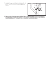
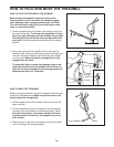
5. Loosen the two (one shown) Crossbar Screws (98) sev-
eral turns. Place the Console Base (87) on the Right
H
andrail (16) and the Left Handrail (not shown). M
ake
sure that the Wire Harness is not pinched in the Right
H
andrail.
A
ttach the Console Base with four 3/4” Screws
(5) (only two Screws are shown).
Start all four 3/4”
Screws before tightening them.
Insert the Wire Harness (53) through the two indicated
plastic ties on the Console Base (87). Next, insert the
Wire Harness up through the opening beside the Wire
Cover (10). Make sure that the Wire Cover is securely at-
tached to the Console Base.
See the inset drawing. Look at the top of the Console
Base (87). Insert the Wire Harness (53) through the plas-
tic tie on top of the Console Base.
53
53
Tie
87
5
85
98