


PROBLEM: The walking belt slows when walked on
S
OLUTION: a
. Use only a single-outlet surge suppressor that meets all of the specifications described on page 8.
b
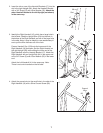
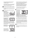
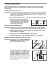
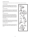
. If the walking belt is overtightened, treadmill perfor-
mance may decrease and the walking belt may be-
come damaged. Remove the key and
UNPLUG
THE POWER CORD. Using the allen wrench, turn
both rear roller adjustment bolts counterclockwise,
1/4 of a turn. When the walking belt is properly tight-
ened, you should be able to lift each side of the
walking belt 2 to 3 inches off the walking platform.
Be careful to keep the walking belt centered. Plug in
the power cord, insert the key, and run the treadmill
for a few minutes. Repeat until the walking belt is
properly tightened.
c. If the walking belt still slows when walked on, please call toll-free 1-800-4-MY-HOME
®
(1-800-
469-4663).
PROBLEM: The walking belt is off-center or slips when walked on
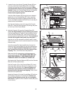
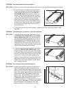
SOLUTION: a. If the walking belt is off-center, first remove the key
and UNPLUG THE POWER CORD. If the walking
belt has shifted to the left, use the allen wrench to
turn the left rear roller bolt clockwise 1/2 of a turn;
if
the walking belt has shifted to the right, turn the
bolt counterclockwise 1/2 of a turn. Be careful not to
overtighten the walking belt. Plug in the power cord,
insert the key, and run the treadmill for a few minutes.
Repeat until the walking belt is centered.
b. If the walking belt slips when walked on, first remove
the key and
UNPLUG THE POWER CORD. Using
the allen wrench, turn both rear roller bolts clockwise,
1/4 of a turn. When the walking belt is correctly tight-
ened, you should be able to lift each side of the walk-
ing belt 2 to 3 inches off the walking platform. Be
careful to keep the walking belt centered. Plug in the
power cord, insert the key, and carefully walk on the
treadmill for a few minutes. Repeat until the walking
belt is properly tightened.
PROBLEM:
T
he upper body arms squeak during use
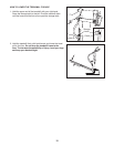
SOLUTION:
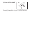
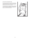
a. Correcting this problem requires a small amount of
white marine grease, available at most hardware
stores. Turn the Resistance Knob (104) counterclock-
wise until it can be removed. Remove the Resistance
Cone (109) and the Upper Body Arm (118), along with
the Resistance Plate (108), Washer (123), Spring
Washer (105), Thrust Washers (107), and Thrust
Bearing (106). (Note: If the Resistance Sleeve [110]
or Resistance Plate [108] comes out of the
Resistance Bracket [111] or Resistance Cone, press it
back in.) Apply a
thin layer of white marine grease to
the outer surface of the Resistance Cone (109).
Reattach all parts in the order shown at the right.
17
b
a
Rear Roller
Adjustment Bolts
2”–3”
b
110
111
118
104
107
105
108
106
a
123
109