


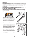

9. Make sure that all parts are properly tightened before you use the treadmill. Note: Extra hardware may
be included. Keep the included allen wrenches in a secure place. The large allen wrench is used to adjust the
walking belt (see page 21). To protect the floor or carpet, place a mat under the treadmill.
47
42
44
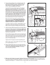
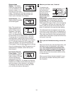
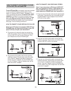
7. Insert the excess Wire Harness (42) into the large hole in
the side of the Right Handrail (72). Securely tighten the
plastic ties on the bottom of the Console Base (47) to
prevent the Wire Harness from slipping.
Then, cut off
the ends of the plastic ties.
Route the Wire Harness (42) through the indicated open-
ing in the Console Base (47). If you connected the Audio
Cable (120) in step 5, route it through the slot in the Wire
Cover (44). Attach the Wire Cover to the Console Base
with a 1/2” Silver Screw (48).
Tighten two 3/4” Screws (2) into the Console Base (47).
Refer to step 3 and 4. Firmly tighten the three 3/4” Bolts
(37) in each Handrail (72, 71).
7
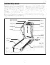
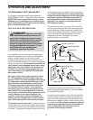
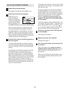
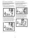
8. Attach a Wheel (66) to the inner side of each Extension
Leg (63) with a Wheel Bolt (64) and a Wheel Nut (13) as
shown. Do not overtighten the Bolts. The Wheels
should be able to spin freely.
63
64
66
13
2
72
48
120
Ties
8
Opening
47
Ties
72
6
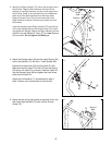
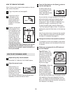
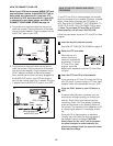
6. Place the Console Base (47) on the Right Handrail (72)
and the Left Handrail (not shown). Attach the Console
Base with four 3/4” Screws (2) (only two Screws are
shown).
Do not overtighten the Screws.
Insert the Wire Harness (42) through the two indicated
plastic ties on the Console Base (47). Next, touch the
Right Handrail (72) to discharge any static. Refer to the
inset drawing. Find the 3-wire connector on the end of the
Wire Harness (42). Insert the connector into the red socket
beneath the console.
The connector should slide easily
into the socket and “snap” into place. If the connector
does not slide easily and snap into place, turn the connec-
tor and then insert it. Insert the 5-wire connector into the
black socket beneath the console in the same way.
Make sure that the connectors and wires appear as
shown at the right.
IF THE CONNECTORS ARE NOT
INSERTED PROPERLY, THE CONSOLE MAY BE
DAMAGED WHEN THE POWER IS TURNED ON.
If you plan to use iFIT.com CDs or videocassettes, or pro-
grams from our Web site (see page 13), plug the Audio
Cable (120) into the jack on the back of the Console (43).
42
43
120
2
5-wire
42
120
3-wire
7