


4
M10 Split Washer (26)Ð5
M10 x 25mm Button Head Screw (25)Ð5
M4 x 16mm Screw (22)Ð4
M10 Nylon Locknut (58)Ð6
M8 Split Washer (41)Ð4
M10 x 45mm Button Head Screw (46)Ð2
M10 x 58mm Carriage Bolt (59)Ð4
M8 Nylon Locknut (20)Ð4
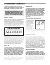
ASSEMBLY
Place all parts of the exercise bike in a cleared area and remove the packing materials. Do not dispose of the
packing materials until assembly is completed. Assembly requires the included tools, two adjustable
wrenches , and a phillips screwdriver .
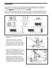
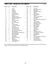
To identify the small parts used in assembly, refer to the drawings below. The number in parenthesis below each
drawing refers to the key number of the part, from the part list on page 11. The second number refers to the
quantity used in assembly. Note: If a part is not in the parts bag, check to see if it has been pre-assembled.
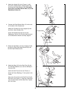
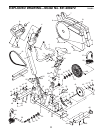
1. Press two 2Ó x 3Ó Endcaps (48) into the Rear
Stabilizer (61).
Position the Rear Stabilizer (61) under the
angled bracket on the rear of the Frame (1).
Make sure that the Rear Stabilizer is turned so
the recessed holes are on the bottom. Attach the
Rear Stabilizer with two M10 x 58mm Carriage
Bolts (59) and two M10 Nylon Locknuts (58).
2. Press two 2Ó x 3Ó Endcaps (48) into the Front
Stabilizer (60). Attach a Wheel (47) to one of the
brackets on the Front Stabilizer with an M10 x
45mm Button Head Screw (46) and an M10
Nylon Locknut (58). Attach a Wheel to the other
bracket on the Front Stabilizer in the same way.
Position the Front Stabilizer (60) under the
angled bracket on the front of the Frame (1).
Make sure that the Front Stabilizer is turned so
the recessed holes are on the bottom. Attach the
Front Stabilizer with two M10 x 58mm Carriage
Bolts (59) and two M10 Nylon Locknuts (58).
61
Recessed
Holes
59
48
1
1
58
58
48
Recessed
Holes
59
1
2
47
60
48
48
58
46