


5
6
17
17
71
71
21
21
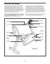
Front
Rear
Side
Side
1
1
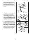
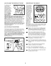
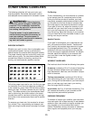
1. Carefully slide the Upright (6) onto the Frame (1).
Be careful to avoid pinching the wires. Loosely
thread four M10 x 25mm Button Screws (71) with
M10 Split Washers (17) through the Upright and into
the Frame. Attach the top of the side shields with
two M4 x 16mm Screws (21). Firmly tighten all four
Button Screws in the following order: front, rear, and
then sides.
22
21
16
18
Hole
6
2
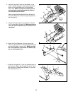
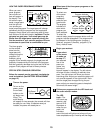
2. While another person holds the Handlebar (16) near
the Upright (6), route the Reed Switch Wire (18) up
through the indicated hole in the Handlebar.
Attach the Handlebar (16) to the Upright (6) with
two M10 x 25mm Button Screws (71) and two M10
Split Washers (17). Make sure that no wires are
pinched between the Handlebar and the Upright.
Next, attach the Tension Control (22) to the Upright
(6) with an M4 x 16mm Screw (21).
71
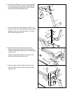
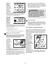
3. The Console (9) requires two “AA” batteries (not
included). Alkaline batteries are recommended. To
install batteries, turn the console over and insert two
batteries into the battery clip as shown in the inset
drawing. Make sure that the negative ends of the
batteries (marked “—”) are touching the springs
in the battery clip.
Attach the Console (9) to the Console Back (30) with
four Console Screws (35), making sure that the indi-
cated wires are extending from the Console Back
(30). Be careful not to pinch the wires.
3
35
Wires
Battery
Clip
Batteries
9
30
17