


7
9
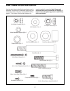
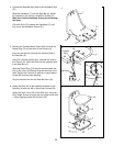
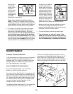
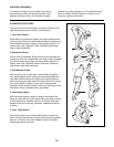
9. Identify the Left Pedal Leg (3) by looking at the
Lock Pin (90) on the pre-assembled Toe Pedal (36).
The Lock Pin must be on the outside when the
Pedal Leg is mounted.
Attach a Pedal (29) to the Left Pedal Leg (3) with three
M4 x 16mm Tapping Screws (30).
Lubricate a Pedal Bolt (8) with the included grease
pack and slide it through the two pre-assembled
Bushings (39). Slide a Plastic Pedal Spacer (42) onto
the Pedal Bolt (8) and slide the Bolt into the hole in the
left Crank Arm (10). Tighten a 1/2Ó Nylon Locknut (9)
onto the Pedal Bolt (8).
Repeat this procedure for the Right Pedal Leg (70, not
shown).
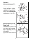
8. Attach the Backrest (40) to the indicated brackets on
the Upright (2) with four M6 x 16mm Seat Screws (28).
8
29
30
8
3
42
39
10
9
36
(90)
Lubricate
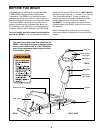
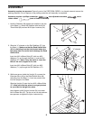
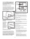
7. Note: The assistance of another person is recom-
mended for this step.
While another person holds the Handlebar (7) in the
position shown, connect the Handlebar Wire (87) to
the Extension Wire (49) extending from the Upright (2).
Next, slide a Plastic Sleeve (53) onto each of the indi-
cated shafts on the Upright (2).
Slide an M10 Washer (71) onto each of the M10 x
25mm Button Head Bolts (85). Next, insert the Bolts
through the brackets on the Handlebar (7) and then
slide an M16 Flat Washer (84) and a Metal Handlebar
Spacer (83) onto each Bolt. Insert the Bolts into the
shafts on the Upright (2) and tighten them with the
included allen wrench. Be careful not to overtighten
the Bolts; the Handlebar must pivot easily.
28
28
40
2
7
71
71
85
84
53
84
83
85
Shaft
Bracket
83
7
53
87
49
2