


8
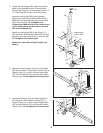
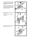
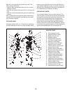
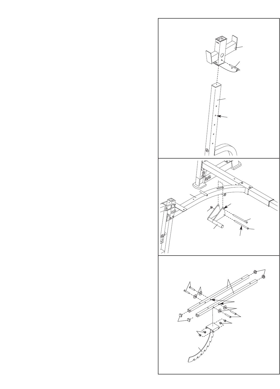
8. Slide the Right Weight Rest (17) onto the Right
Upright (5). Insert the Weight Rest Pin (43) into
the W
eight Rest and an adjustment hole in the
Upright from the side shown. Rotate the Pin down
so that it wraps around the back of the Upright.
Repeat this step with the Left Weight Rest
(not shown) and the Left Upright (not shown).
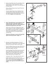
9. Lubricate an M10 x 88mm Button Bolt (42) with
grease. Attach the Adjustment Lever (29) to the
tube on the bottom of the Bench Frame (1) with
the Bolt and an M10 Nylon Locknut (56). Do not
overtighten the Locknut; the Lever must be
able to pivot easily.
Hold the handle on the Adjustment Lever (29) so
that the upper hole is above the Bench Frame
(1). Slide the M10 x 72mm Flat Head Screw (46)
through the indicated side of the Lever, over the
Bench Frame,and tighten it into the other side of
the Adjustment Lever. Make sure that the
threads of the Screw show through the
Adjustment Lever.
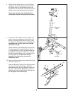
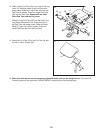
10.
Press four 25mm Square Inner Caps (26) into the
Backrest
T
ubes (10).
Orient the Backrest Tubes (10) so that the indicat-
ed holes are closer to the bottom.
Attach the
Backrest Bracket (16) to the Backrest Tubes with
four M10 x 43mm Button Bolts (49), four M10
W
ashers (53), and four M10 Nylon Locknuts (56).
Do not tighten the Locknuts yet.
8
9
10
43
17
5
Adjustment
Hole
Lubricate
42
46
56
1
29
Upper
Hole
26
26
10
Holes
53
49
53
49
56
56
16