


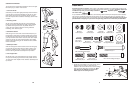
50
8
38
22 7
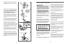
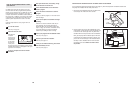
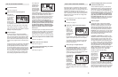
6. Whilst another person holds the Console (23) in the
position shown, connect the wire harness on the
Console to the Extension W
ire Harness (44). Insert the
excess wire harness into the Upright Extension (73).
Attach the Console (23) to the Upright Extension (73)
with three M10 x 27mm Button Screws (67) and three
M10 Split Washers (59).
Be careful to avoid pinching
the wire harnesses.
Snap the bookrack onto the Console (23) in the indicat-
ed location.
6
23
67
73
59
59
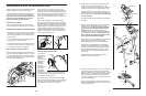
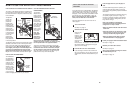
7. Identify the Left Handlebar (6), which is marked with a
sticker. Insert the Left Handlebar into one of the
Handlebar Legs (5);
make sure that the Handlebar
Leg is turned so the hexagonal holes are on the
indicated side. Attach the Left Handlebar to the
Handlebar Leg with two M8 x 45mm Button Bolts (50)
and two M8 Nylon Locknuts (38).
Make sure that the
Nylon Locknuts are inside of the hexagonal holes.
Do not fully tighten the Button Bolts yet.
Apply a light coat of the included grease to the left axle
on the Upright (2) and inside of the two Small
Handlebar Bushings (49) in the Left Handlebar (6).
Carefully slide an Upright Spacer (48), a Handlebar
Spacer (47), the Left Handlebar (6), and a Handlebar
Cap (46) onto the left axle on the Upright (2) as shown.
Slide a Handlebar Washer (55) onto an M8 x 19mm
Shoulder Screw (56), and tighten the Shoulder Screw
into the axle.
Assemble the Right Handlebar (8) and the other
Handlebar Leg (5) in the same way.
Grease
7
44
Wire Harness
67
Bookrack
67
47
49
5
2
5
55
46
56
6
48
8
80
81
78
1
1
13
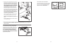
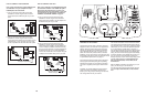
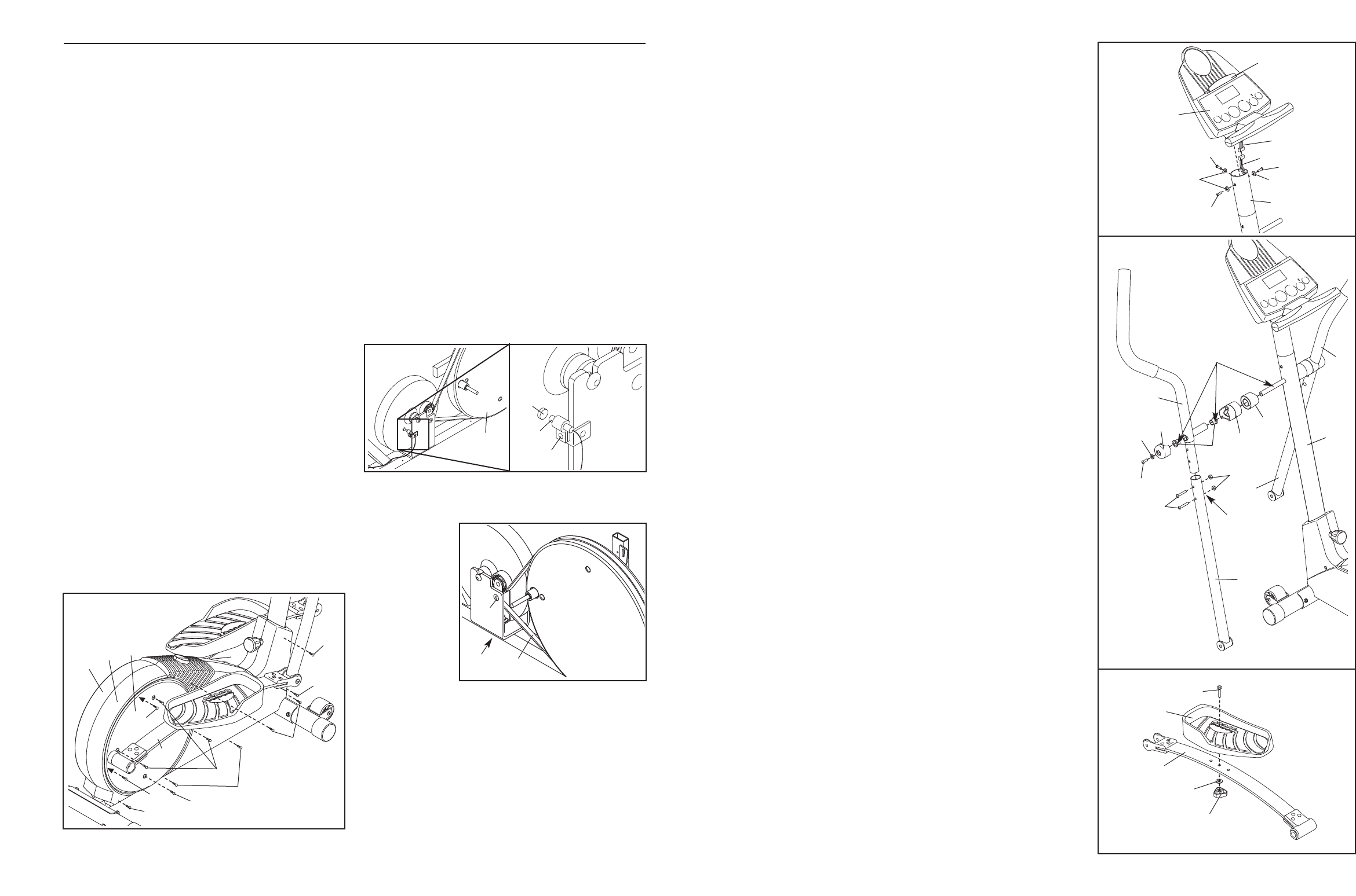
8. Identify the left Pedal Spring (11), which is marked with
a sticker. Attach the Left Pedal (13) to the left Pedal
Spring with an M10 x 27mm Carriage Bolt (80), an M10
W
asher (78), and a Pedal Knob (81) as shown. Note:
The Left Pedal can be attached in several positions
using the five positions in the Left Pedal and the three
holes in the Pedal Spring.
Attach the Right Pedal (not shown) in the same way
.
Make sure that both Pedals are in the same hole and in
the same pedal position.
Hexagonal
Holes
Inspect and tighten all parts of the elliptical crosstrainer
regularly. Replace any worn parts immediately.
To clean the elliptical crosstrainer, use a damp cloth
and a small amount of mild detergent. Important:
Keep liquids away from the console and keep the
console out of direct sunlight. During storage,
remove the batteries from the console.
BATTERY REPLACEMENT
If the console display becomes dim, the batteries
should be replaced. See assembly step 5 on page 6.
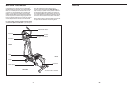
HANDGRIP PULSE SENSOR TROUBLESHOOTING
• Avoid moving your hands whilst using the handgrip
pulse sensor; excessive movement may interfere
with heart rate readings. Do not hold the metal con-
tacts too tightly.
• For the most accurate heart rate reading, hold the
metal contacts for about 15 seconds.
• For optimal performance of the handgrip pulse sen-
sor, clean the metal contacts with a soft cloth—do
not use alcohol, abrasives, or chemicals.
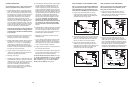
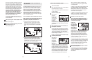
HOW TO ADJUST THE REED SWITCH
If the console does not display correct feedback, the
reed switch should be adjusted. To do this, you must
remove the Pedal Springs (11), the right Pedal Disc
(15), and the Side Shields (3, 4). See step 9 on page
8 and remove the Pedal Springs.
Next, remove the four Screws (51) from the right
Pedal Disc (15), and slide the Pedal Disc off. Remove
all Screws (52, 64) from the Right Side Shield (4) and
the two Screws (77) from beneath the Pedal Disc, and
remove the Right Side Shield. Remove all Screws
(52) from the Left Side Shield (3) and remove the Left
Side Shield.
Next, see the drawing below and locate the Reed
Switch (53). Loosen, but do not remove, the indicated
M4 x 16mm Screw (52). Slide the Reed Switch slightly
toward or away from the Magnet (58) on the flywheel.
Retighten the Screw. Turn the left Pedal Disc (15) for a
moment. Repeat until the console displays correct
feedback. When the Reed Switch is correctly adjusted,
reattach the Side Shields (3, 4), the right Pedal Disc
(15), and the Pedal Springs (11).
HOW TO ADJUST THE DRIVE BELT
If you can feel
the pedals slip
whilst you are
pedalling,
even when the
resistance is
adjusted to
the highest
level, the
Drive Belt (19)
may need to
be adjusted.
T
o adjust the
Drive Belt, you must first remove both side shields.
See HOW
T
O
ADJUST
THE REED SWITCH at the
left and remove the side shields.
Next, loosen the M8 x 22mm Flat Head Screw (68)
and turn the M10 x 70mm Bolt (62) until the Drive Belt
(19) is tight. When the Drive Belt is tight, tighten the
Flat Head Screw. Reattach the side shields.
MAINTENANCE AND TROUBLESHOOTING
64
77
51
51
77
52
52
64
64
11
1
1
4
15
3
58
53
52
15
68
62
19