


page 7
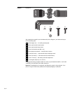
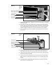
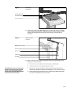
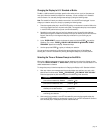
19. Install the incline crank handle (M9.1 only) onto the lift column shaft as shown in Diagram 7.
Align the handle with the
flat
portion of the shaft end. Insert a screw (D) through the handle
and crank shaft and tighten the screw securely with the hex key (G) provided.
Do not
overtighten.
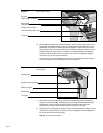
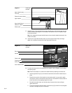
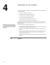
20. Attach the lift column trim by following these steps. While performing these steps, refer to
Diagram 8 for further clarification.
a. Position the trim strip so that the notched end points up. See Diagram 8.
b. Insert the base of the trim through the opening in the hood.
c. Raise the trim until the notched end of the trim touches the underside of the upper
handrail clamp. Be careful to maintain vertical alignment of the trim with the lift column.
d. While maintaining alignment, attach the trim by pressing firmly against the lift column
until the Velcro pads fasten securely to each other.
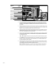
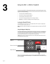
ERGO/SMART
DISTANCE
TIME
SPEED
CALORIES
INCLINE
MODE
SPEED
STOP
HOLD TO RESET
MODE
ENTER
ACTIVATE OFF
CAUTION
Keep hands and clothing away from
bed, belt and rear roller when treadmill
is in operation. As with any power
drivern equipment, DO NOT allow
children and persons unfamiliar with
operation on or near this treadmill.
Always straddle belt when starting
the treadmill. Step onto belt only at
speeds 1mph and slower.
Diagram 7
Install incline
crank handle
Incline crank handle
Incline handle screw
Incline crank shaft
Diagram 8
Attach trim strip to
lift column
Ribbon cable
Trim strip
Lift column
Velcro strip
Notched end of trim strip
CAUTION: Make sure that the ribbon cable is
situated in the trim strip’s center slot before
you take the next step. Cables crimped or
pinched due to inaccurate assembly may not
be covered by the limited warranty.