


page 8
®
®
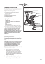
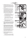
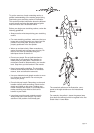
13. Secure the axle. Diagram 10. Make sure that
the foot rests are securely fastened to the axle
and the axle is centered through the seat frame.
Use the 3mm hex key to tighten the two small
set screws that hold the axle in position. Do not
overtighten the screws.
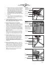
14. Secure the handlebar. Diagram 11. Prior
to tightening the handlebar bolts, slide the
handlebar caps into the upright supports.
Then, securely tighten the bolts using the
6mm hex key.
15. Return to the seat bracket bolts. Use the hex
key to securely tighten the 4 seat bracket bolts.
Do not tighten the bolts so severely that you
compress or crack the plastic alignment bracket.
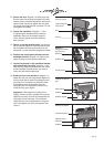
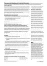
16. Position the instructional placard onto the
handlebar bracket. Diagram 12. Remove the
paper backing from the double-sided tape.
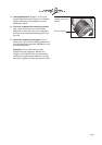
17. Center the placard on the handlebar bracket
and press firmly into place. Diagram 13. Be
sure that the placard is positioned in the center
of the handlebar bracket before you press it
firmly onto the double-sided tape.
18. Install the rear level adjustors. Diagram 14.
Raise the rear end of the equipment slightly off
the floor and slide a rubber level adjustor onto
one side of the rear base rail. Slide the other
level adjustor onto the opposite base rail.
Carefully lower the equipment onto the floor.
Avoid pinching your fingers.
Important: If the equipment is placed on a
slightly, uneven surface, rotating the rear level
adjustors can help, but will not compensate for
extremely uneven surfaces. The maximum
height that you can compensate for using the
rear level adjustors is about one quarter inch
(6 mm).
Diagram 12
Exposing the adhesive
tape.
Paper backing
Handlebar
Diagram 13
Attaching the placard.
Handlebar
Instructional placard
Adhesive double-
sided tape
Handlebar Bracket
Diagram 10
Securing the axle.
Axle
Tighten screw with
3mm hex key
Foot rest
Diagram 11
Sliding the handlebar
caps into place.
Handlebar cap
Wrist strap
Upright support