


945101 POWER RACK ASSEMBLY INSTRUCTIONS
:::::::::::::::::::::::::::::::::::::::::::::::::: ........................
" ....
:: ~::: :::::::::::::::::::::: ::i ~:!:i ~:i~i~i~i~i:!~!~ii~!~:~...!~i~:.~!~i~i:...:::!~i~i:i~!:i::.:.i~i:~i~::i:!~:i~ :!.-’.’:~::::i::::i:.::!: >.’~!~.~>.’-’.’:~.~.: ~:
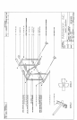
1. Insert eight (8) 3 X 2 IN END CAPS into the ends of the IYPRIGI:IT FRAME WELDMENTI$ as shown
on drawing.
2. LOOSELY assemble the LOWER CONNECTOR WELDMENT and the UPPER CONNE~TOR
WELDMENT between each UPRIGHT FRAME WELDMENT as shown on drawing.
3. Insert four (4) 1-1./4 IN RD END CAPS into the ends of the TUBES on the CHIN-10P CONNECTOR
WELDMENT as shown on drawing.
4.
LOOSELY asserable the C~IN-UP CONNECTOR WELDMENT between the LrPRIGI~IT FRAME
WELDMENTS as shown on drawing.
5.
Insert two (2) 1-314 IN KID END CAPS into the ends of the PLATE I~OLDER WELDMENTS as shown
on drawing,
6. LOOSELY assemble the PLATE I:IOLDER WELDMENTS to the UPRIGHT FRAME
WELDMENTS as shown on drawing.
7.
When all compnne, nts are assembled, SECURELY tighten all bolt connections.
8.
Attach twelve (12) 1-1/2 X 2 IN GLIDES (three each) to the SAFETY BAR WELDMENTS and
SUPPORT WELDMENTS as shown in (DETAIL A).
9. Insert the BAR SUPPORT WELDMENT, and the SAFETY BAR WELDMENT into the desi.red hole
setting as shown ola drawing and in (DETAIL B).
Part # 6645801
3 Revision: 07/15/96