


~THERE IIS A RISK ASSUMED BY INDIVIDUALS WHO USE THIS TYPE
OF EOUIPMENT. TO MINIMIZE RISK. PLEASE FOLLOW THESE Rr~ES:
1. Consult your physician before beginning any excercise program
.
.
’ 2. Inspect .equipment daily. Tighten all loose connections and replace warn pa~ immediately.
Failure llo do so may result in serious injury ....
3.
Do not allow minors or children to play on or around this equipment.
4.
Excer¢ise with care to avoid injury.
5. If unsur,~ of proper use of equipment, call your local ParaBody distributor or call the ParaBody
customer service deparhnent at 1-800-328-9714. ..
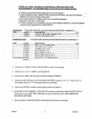
PARTS LIST: ***PLEASE IDENTIFY ALL PARTS BEFORE BEGINNING ASSEMBLY***
ITEM PART #
DESCRIPTION
OTY
I ..........................65~9903 ..............
WLDMT, DIP HANDLE SUPPORT WHT ...........................................
2 ..........................6590303 ..............
WLDMT, DIP HANDLE WHT .............................................................
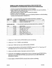
HARDWARE LIS’]~
***PLEASE SORT HARDWARE BEFORE BEGINNING ASSEMBLY***
ITEM
PART #
DESCRIPTION
OTY
1 ..........................3103101 ............ ,. GRIP, I-1/4 X 5 CLOSED END ...........................................................
2.
2 ..........................6405201 .............. CAP, END 2 SQ. 10-14 GA ..................................................................
3.
3 ..........................3102502 ............. WASHER, FLAT 1/2 ID ..................................................................
, ....
4.
4~ ..~, ....................310280I..~ ........... NUT, NYLOCK i/2-13 ..~., ............
i.:., .......
~ ........................................
2.
5 ..........................
3102910 .............. BOLT, HHG2 1/2-13 X 3 ......................................................................
2.
6 ..........................
61,45801 .............. KNOB, 3 PRONG 3/8-16 X 3/4..~ .........................................................
1 .
7 ..........................
3120801 .............. PIN, DETENT .390 DIA X 4-I/2 ..........................................................
1.
8 ..........................
6600301 .............. GLIDE, 3.75 X 3.75 UHMWPE QTY1 ................................................
2.
1.
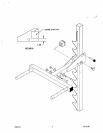
Attach two 2" END CAPS to DIP HANDLE as shown on drawing.
2.
Attach one 1-1/4 x 5" GKIP to each HANDLE.
3. Insert one 2" IEND CAP into end of DIP HANDLE SUPPORT.
4.
Assemble DIP HANDLE to DIP HANDLE SUPPORT using two 1/2" x 3" bol~s, four 1/2"
flat washers and two 1/2" lock nuts as shown on drawing.
5. Attach one GLIDE to inside of each plate as shown in Detail A.
6.
Install DIP ATTACHMENT to GUN RACK as shown on drawing. Insert DETENT PIN in
first hole for use on 893 PRO SYSTEM, and second hole for use on 866 STRENGTH
BUILDING SYSTEM.
7. Securly tighten 3 PRONG KNOB in threaded hole as shown on drawing.
6600101
2 03/22/96