7
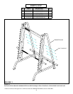
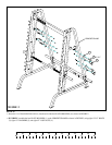
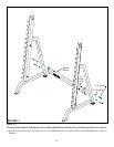
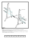
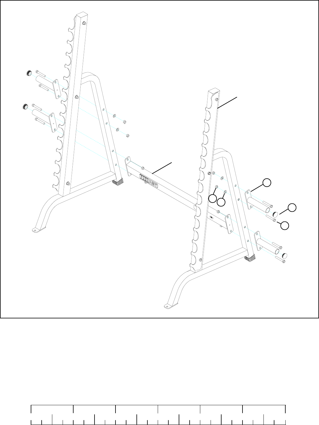
FIGURE 2
STEP 2:
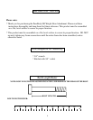
0
1
2
345
6
1/2 1/2 1/2 1/2 1/2 1/2
• Insert four 1-3/4” ROUND END CAPS (5) into the end of the four PLATE HOLDERS (1) as shown in FIGURE 2.
• SECURELY assemble two PLATE HOLDERS (1) and the CROSS BRACE to the UPRIGHT FRAMES as shown in FIGURE 2, using
four 1/2 X 3” BOLTS (2) and four 1/2” LOCK NUTS (4).
2 1/2 X 3”
5
1
UPRIGHT FRAME
CROSS
BRACE
• SECURELY assemble the two PLATE HOLDERS (1) to the UPRIGHT FRAMES as shown in FIGURE 2, using four 1/2 X 3” BOLTS
(2), four 1/2” WASHERS (3), and four 1/2” LOCK NUTS (4).
4
3


