


4
PARTS LIST
0
1
2
345
6
1/2 1/2 1/2 1/2 1/2 1/2
PART #
LEA6215709
LEA6284710
LEA6013709
LEA3235214
LEA3114403
LEA3114702
KEY
1
2
3
4
5
6
QTY
1
1
1
2
4
2
PART #
LEA6011401
LEA6405201
LEA6236701
LEA6177001
DESCRIPTION
SAFETY LOCK PIN
2” SQ. END CAP
1-3/4” SQ. END CAP
2-1/2 X 5-1/2” NON SKID STP
QTY
1
1
1
4
DESCRIPTION
FOOT BRACE ASSY
ADJUSTABLE TUBE ASSY
CONNECTOR PLATE
3/8 X 3-1/2” BOLT
3/8” FLAT WASHER
3/8” LOCK NUT
KEY
7
8
9
10
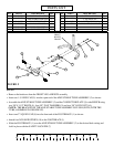
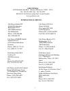
STEP 5:
FIGURE 5
• Remove the hardware from the FRONT LEG of BENCH assembly
• Insert one 1-3/4 END CAP (9) into the open end of the ADJUSTABLE TUBE ASSEMBLY (2) as shown
• Assemble the ADJUSTABLE TUBE ASSEMBLY (2) and the CONNECTOR PLATE (3) to the BENCH using
two 3/8 X 3-1/2” BOLTS (4), four 3/8” FLAT WASHERS (5) and two 3/8” LOCK NUTS (6).
(NOTE: THE BRACKET ON THE ADJUSTABLE TUBE ASSEMBLY IS FLUSH (EVEN) WITH THE
TUBE, ASSEMBLE FLUSH SIDE UP)
• Insert one 2” SQ END CAP (8) into the front end of the FOOT BRACE (1) as shown
• Attach four NON SKID STRIPS (10) to the FOOT BRACE (1)
• Slide the FOOT BRACE (1) over the ADJUSTABLE TUBE ASSEMBLY (2) to the desired hole setting and
hold in place with the SAFETY LOCK PIN (7)
3
6
1
8
2
4
10
9
5
7
FRONT
BENCH
FRAME