


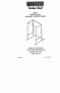

843101 POWER RACK ASSEMBLY INSTRUCTIONS
9.
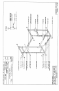
Slide four (4) 2 IN SQ COVEK CAPS over the en& of each UPRIGHT BASE WELDMENT as shown
on drawing.
LOOSELY assemble the LOWER CONNECTOR WELDMENT between e~tch UPRIGIlT BASE
WELDMENT as shown on drawing.
Insert twelve (12) 3 X 2 IN INSEKT GUIDES into the ends of each SAFETY trAIL WELDMENT and
each BAR SUPPORT WELDMENT as shown in (DETAIL A). NOTE: MAKE SURE Tile
INSERT GUIDES SNAP INTO Tile ilOLES OF THE WELDMENTS.
SECURELY assemble the six (6) SPRING PIN ASSEMBLIES to the SPRING PIN BARRELS on each
SAFETY RAIL WELDMENT and each.BAR SUPPORT WELDMENT as shown in (DETAIL A).
Slide one (1) BAR SUPPORT WELDMENT and one (I) SAFETY RAIL WELDMENT (IN
ORDER) onto each UPRIGHT WELDMENT as shown on drawing.
Insert four (4) 2 IN SQ END CAPS into the ends of the UPRIGHT WELDMENT as shown on drawing.
LOOSELY assemble each UPRIGHT WELDMENT to the UPRIGHT BASE WELDMENTS as
shown on drawing.
LOOSELY assemble the UPPER CONNECTOR WELDMENT and the CK[,~ BAR WELDMENT
between the UPRIGHT WELDMENTS as shown on drawing.
When all components are assembled, SECURELY tighten all bolt connections.
Part # 6612301 3
Revision: 06/25/96